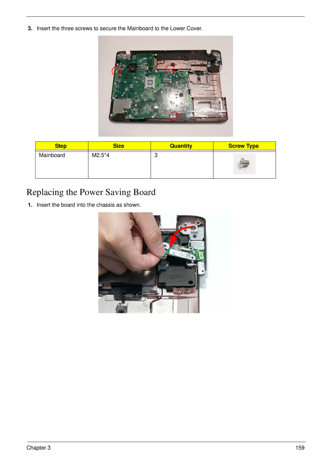
Manuals
/
Brands
/
Computer Equipment
/
Laptop
/
Acer
/
Computer Equipment
/
Laptop
Acer
8935G
- page 169
1
169
320
320
Download
320 pages, 10.21 Mb
Chapter 3
159
3.
Insert the three screws to secure the Mainboard to the Lower Cover.
Replacing the Power Saving Board
1.
Insert the board into the chassis as shown.
Step
Size
Quantity
Screw Type
Mainboard M2.5*4
3
Contents
Main
Page
Copyright
Disclaimer
Conventions
Preface
Page
System Specifications 1
System Utilities 35
Machine Disassembly and Replacement 53
Page
Troubleshooting 195
Jumper and Connector Locations 211
FRU (Field Replaceable Unit) List 215
Page
System Specifications
Chapter 1
Features
Page
Special keys and controls
I/O interface
Environment
4Chapter 1
System Block Diagram
(OZ888GS0LN)
PCIE-1
Bluetooth
FingerPrint
Your Acer Notebook tour
Front View
Page
Closed Front View
Rear View
Left View
Right View
Bottom View
TouchPad Basics
Using the Keyboard
Key Types
Windows Keys
System Hotkeys
Using the System Utilities
Acer GridVista (dual-display compatible)
Hardware Specifications and Configurations
Page
Page
Page
Page
Page
22 Chapter 1
Hard Disk Drive Interface
Hard Disk Drive Interface (contd.)
Chapter 1 23
24 Chapter 1
Chapter 1 25
26 Chapter 1
Chapter 1 27
Page
Page
Page
Page
Page
Page
Page
System Utilities
Chapter 2
BIOS Setup Utility
Navigating the BIOS Utility
Information
Main
Security
Setting a Password
Removing a Password
Changing a Password
Boot
Exit
BIOS Flash Utilities
DOS Flash Utility
Page
Page
Remove HDD/BIOS Password Utilities
Page
Page
Using DMITools
Read DMI Information from Memory
Write Product Name to EEPROM
Write Serial Number to EEPROM
4). Write UUID to EEPROM (Create UUID from Intel WFM20.pdf)
Using the LAN MAC EEPROM Utility
Page
Machine Disassembly and Replacement
Chapter 3
Disassembly Requirements
General Information
Pre-disassembly Instructions
Disassembly Process
External Module Disassembly Process
External Modules Disassembly Flowchart
Page
Page
Page
Page
Page
Page
Page
Page
Page
Page
Page
Page
Page
Page
Page
Main Unit Disassembly Process
Upper Cover Disassembly Flowchart
Lower Cover Disassembly Flowchart
Page
Page
Removing the Switch Cover
Page
Page
Page
Page
Page
Removing the Upper Cover
Page
Page
Page
Page
Page
Page
Page
Page
Page
Page
Page
Page
Page
Page
Page
Page
Page
Page
Page
Page
Page
Page
Page
Page
Page
Page
Page
Page
Page
Removing the Thermal Module
Removing the Graphics Card Heatsink
Page
Page
LCD Module Disassembly Process
Standard Bezel LCD Module Disassembly Flowchart
Removing the Standard LCD Bezel
Page
Page
Removing the LCD Panel
Page
Page
Page
Page
Flush Bezel LCD Module Disassembly Flowchart
Page
Page
Removing the Flush LCD Bezel
Page
Removing the LCD Panel
Page
Page
Page
Page
LCD Module Reassembly Procedure
Standard Bezel LCD Module ReassemblyLCD Panel
Page
Page
Page
Page
Page
Page
Page
Page
Page
Page
Page
Page
Page
Page
Page
Replacing the Graphics Card Heatsink
Replacing the Thermal Module
Page
Page
Replacing the Subwoofer
Page
Page
Page
Page
Page
Page
Page
Page
Page
Page
Page
Page
Page
Page
Page
Page
Page
Page
Page
Page
Page
Replacing the Upper Case
Page
Page
Replacing the LCD Module
Page
Page
Page
Page
Page
Page
Page
Page
Page
Page
Page
Page
Page
Page
Page
Troubleshooting
Chapter 4
Common Problems
Power On Issue
Computer Shuts down Intermittently
No Display Issue
No POST or Video
Abnormal Video Display
Random Loss of BIOS Settings
Chapter 4 199
LCD Failure
Built-In Keyboard Failure
Chapter 4 201
TouchPad Failure
Internal Speaker Failure
Sound Problems
Internal Microphone Failure
Microphone Problems
HDD Not Operating Correctly
USB (Right Up/Down Side) Failure
Other Failures
Intermittent Problems
Undetermined Problems
Post Codes
Chipset POST Codes
Page
Page
Page
Jumper and Connector Locations
Chapter 5
Top View
Bottom View
Clearing Password Check and BIOS Recovery
Clearing Password Check
BIOS Recovery by Crisis Disk
BIOS Recovery Boot Block:
BIOS Recovery Hotkey:
Steps for BIOS Recovery by USB flash crisis disk:
FRU (Field Replaceable Unit) List
Chapter 6
Acer SM80 Exploded Diagrams
Main Chassis
LCD Assembly
LCD Assembly (Non-Bezel)
Acer SM80 FRU List
Page
Page
Page
Page
Page
Page
Page
Page
Screw List
Page
Appendix A 230
Model Definition and Configuration
Appendix A
Acer SM80 Series
231 Appendix A
Appendix A 232
233 Appendix A
Appendix A 234
235 Appendix A
Appendix A 236
237 Appendix A
Appendix A 238
239 Appendix A
Appendix A 240
241 Appendix A
Appendix A 242
243 Appendix A
Appendix A 244
245 Appendix A
Appendix A 246
247 Appendix A
Appendix A 248
249 Appendix A
Appendix A 250
251 Appendix A
Appendix A 252
253 Appendix A
Appendix A 254
255 Appendix A
Appendix A 256
257 Appendix A
Appendix A 258
259 Appendix A
Appendix A 260
261 Appendix A
Appendix A 262
263 Appendix A
Appendix A 264
265 Appendix A
Appendix A 266
267 Appendix A
Appendix A 268
269 Appendix A
Appendix A 270
Test Compatible Components
Appendix B
272 Appendix B
Microsoft Windows Vista Environment Test
Adapter
Appendix B 273
Audio Codec
Battery
274 Appendix B
Bluetooth
Camera
Appendix B 275
Card Reader
CPU
276 Appendix B
Appendix B 277
278 Appendix B
Appendix B 279
Finger Print Reader
HDD1
280 Appendix B
Appendix B 281
282 Appendix B
Appendix B 283
284 Appendix B
HDD2
Appendix B 285
286 Appendix B
Appendix B 287
288 Appendix B
Appendix B 289
290 Appendix B
Keyboard
LAN
Appendix B 291
LCD
Memory
292 Appendix B
Appendix B 293
294 Appendix B
Appendix B 295
296 Appendix B
Northbridge Chipset
ODD
Appendix B 297
298 Appendix B
Appendix B 299
Remote Control
300 Appendix B
Appendix B 301
Southbridge Chipset
Software
302 Appendix B
TV Antenna
TV Tuner
VGA Chip
VRAM
Appendix B 303
WiFi Antenna
WLAN
304 Appendix B
Online Support Information
Appendix C
Page
Index
A
B
K
C
L
M
N
O
P
T
U
V
W