Removing the Switch Cover
1.See “Removing the Battery Pack” on page 56.
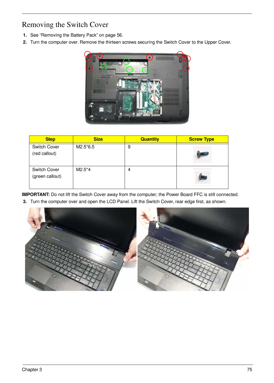
2.Turn the computer over. Remove the thirteen screws securing the Switch Cover to the Upper Cover.
Step | Size | Quantity | Screw Type |
|
|
|
|
Switch Cover | M2.5*6.5 | 9 |
|
(red callout) |
|
|
|
|
|
|
|
Switch Cover | M2.5*4 | 4 |
|
(green callout) |
|
|
|
|
|
|
|
IMPORTANT: Do not lift the Switch Cover away from the computer; the Power Board FFC is still connected.
3.Turn the computer over and open the LCD Panel. Lift the Switch Cover, rear edge first, as shown.
Chapter 3 | 75 |