Chapter 5
Jumper and Connector Locations
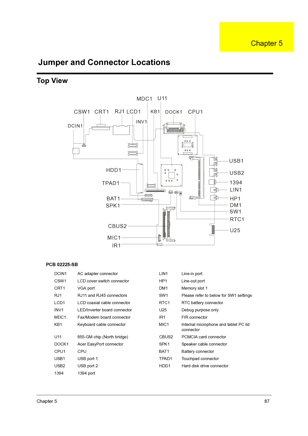
Top View
MDC1 U11
CSW1 CRT1 RJ1 LCD1 KB1 DOCK1 CPU1
DCIN1
INV1
USB1
HDD1
TPAD1
BAT1
SPK1
CBUS2
MIC1
IR1
USB2
1394
LIN1
HP1
DM1
SW1
RTC1
U25
PCB 02225-SB
DCIN1 | AC adapter connector | LIN1 | |
CSW1 | LCD cover switch connector | HP1 | |
CRT1 | VGA port | DM1 | Memory slot 1 |
RJ1 | RJ11 and RJ45 connectors | SW1 | Please refer to below for SW1 settings |
LCD1 | LCD coaxial cable connector | RTC1 | RTC battery connector |
INV1 | LED/Inverter board connector | U25 | Debug purpose only |
MDC1 | Fax/Modem board connector | IR1 | FIR connector |
KB1 | Keyboard cable connector | MIC1 | Internal microphone and tablet PC lid |
|
|
| connector |
U11 | CBUS2 | PCMCIA card connector | |
DOCK1 | Acer EasyPort connector | SPK1 | Speaker cable connector |
CPU1 | CPU | BAT1 | Battery connector |
USB1 | USB port 1 | TPAD1 | Touchpad connector |
USB2 | USB port 2 | HDD1 | Hard disk drive connector |
1394 | 1394 port |
|
|
Chapter 5 | 87 |