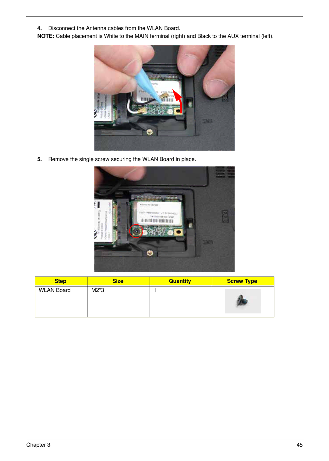
4.Disconnect the Antenna cables from the WLAN Board.
NOTE: Cable placement is White to the MAIN terminal (right) and Black to the AUX terminal (left).
5.Remove the single screw securing the WLAN Board in place.
Step |
| Size | Quantity | Screw Type |
|
|
|
|
|
WLAN Board | M2*3 |
| 1 |
|
|
|
|
|
|
Chapter 3 | 45 |