LCD Module Disassembly Process
IMPORTANT: Cable paths and positioning may not represent the actual model. During the removal and replacement of components, ensure all available cable channels and clips are used and that the cables are replaced in the same position.
NOTE: The product previews seen in the disassembly procedures may not represent the final product color or configuration. The following procedure outlines the steps to disassemble the LCD Module on models with 3G functionality. Models that do not support 3G do not require the removal of the yellow and blue Antenna cables detailed below.
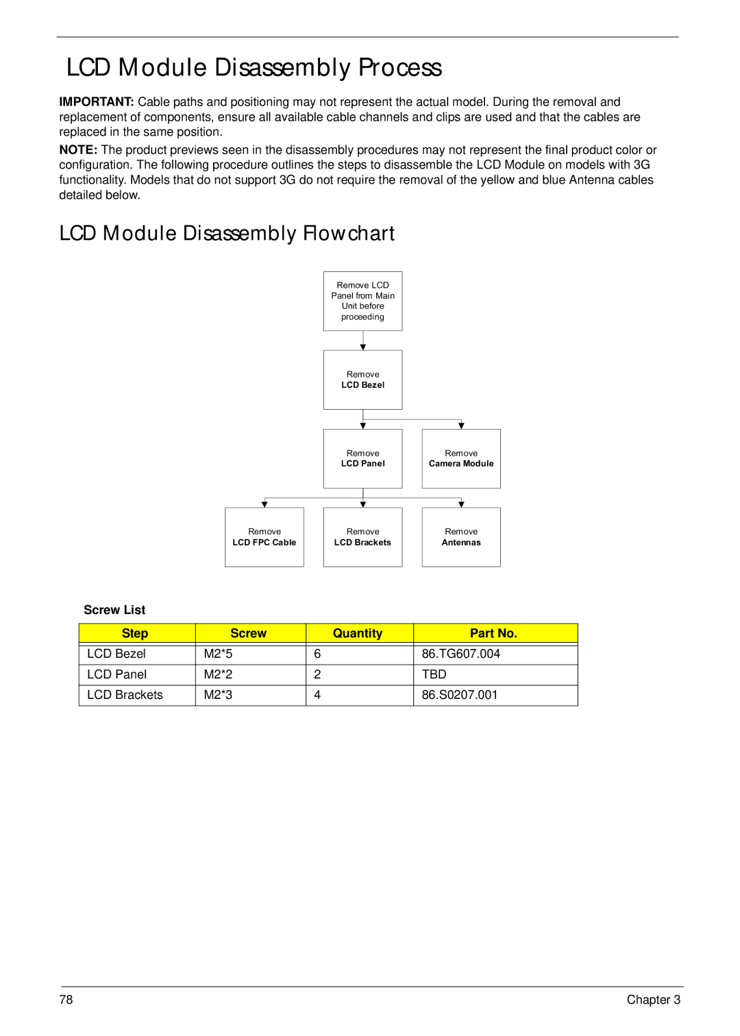
LCD Module Disassembly Flowchart
Remove LCD
Panel from Main
Unit before proceeding
Remove
LCD Bezel
Remove
LCD Panel
Remove
Camera Module
Remove
LCD FPC Cable
Remove
LCD Brackets
Remove
Antennas
Screw List
Step | Screw | Quantity | Part No. |
|
|
|
|
LCD Bezel | M2*5 | 6 | 86.TG607.004 |
LCD Panel | M2*2 | 2 | TBD |
|
|
|
|
LCD Brackets | M2*3 | 4 | 86.S0207.001 |
|
|
|
|
78 | Chapter 3 |