Manuals
/
Acer
/
Computer Equipment
/
Laptop
Acer
LT31
manual
Disconnect the FFC and remove the Keyboard Chapter
Models:
LT31
1
61
180
180
Download
180 pages
52.04 Kb
58
59
60
61
62
63
64
65
Troubleshooting
Specs
System Block Diagram
Bluetooth
Password
Euro symbol
Indicators
Wireless LAN
Common Problems
Bios Setup Utility
Page 61
Image 61
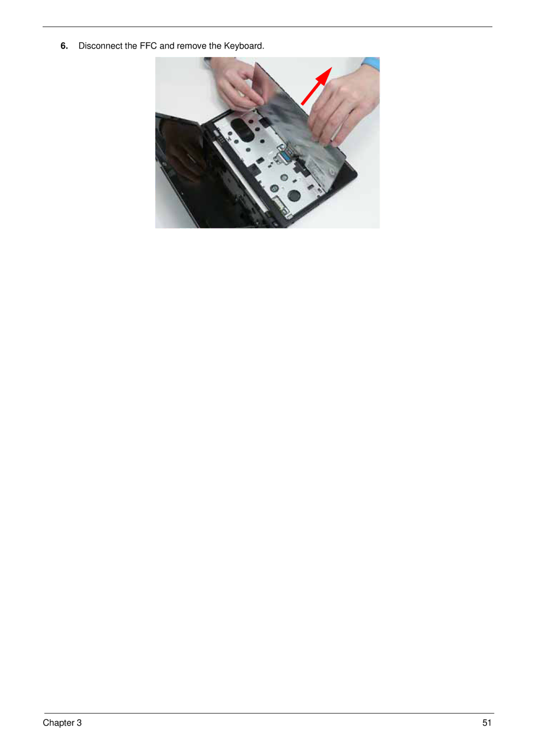
6.
Disconnect the FFC and remove the Keyboard.
Chapter 3
51
Page 60
Page 62
Page 61
Image 61
Page 60
Page 62
Contents
Gateway LT31 Series Service Guide
Revision History
Copyright
Conventions
Preface
Page
Table of Contents
Troubleshooting 125
Model Definition and Configuration 156
Table of Contents
Chapter
Features
Privacy control
AMD S1g1
System Block Diagram
Front View
Your Gateway Notebook tour
Icon Description
Left View
Closed Front View
Right View
Rear and Base View
Icon Function Description
Indicators
Function Left Button Right Button Main TouchPad
TouchPad Basics
Lock Keys and embedded numeric keypad
Using the Keyboard
Key Description
Windows Keys
Hotkey Icon Function Description
Hot Keys
Special Keys
Euro symbol
Processor Specification
Hardware Specifications and Configurations
Processor Specifications
North Bridge Specifications
Hard Disk Drive Interface Specification
System Memory Specification
WD1600BEVT WD2500BEVT MK1655GSX MK2555GSX
LED Specifications
Audio Codec and Amplifier Specification
Bluetooth Specification
LAN Interface Specification
Keyboard Specification
Camera Specifications
Mini Card Specification
Wireless LAN Specification
802.11g
3G Module Battery Specification Cell
Chapter
Navigating the Bios Utility
Bios Setup Utility
Parameter Description
Information
Parameter Description Format/Option
Main
Security
Enabled or
Parameter Description Option
Clear or Set
Enter New Password
Continue
USB CD/DVD
Boot
Exit
Security Boot Exit Exit Saving Changes
Bios Flash Utility
DOS Flash Utility
Information Main Security Boot Exit
Page
WinFlash Utility
Removing HDD Password
Remove HDD/BIOS Password Utilities
Removing Bios Passwords
Related Information
Disassembly Requirements
Disassembly Process
Pre-disassembly Instructions
General Information
Main Screw List Quantity Part Number
External Modules Disassembly Flowchart
External Module Disassembly Process
Screw List Step Quantity
Removing the Battery Pack
Removing the Hard Disk Drive Module
Step Size Quantity Screw Type HDD Module M2*3
Step Size Quantity Screw Type HDD Carrier M3*0.5+3.5I
Removing the Dimm Module
Page
Removing the Wlan Board
Step Size Quantity Screw Type Wlan Board M2*3
Remove the Wlan Board from the Mainboard
Removing the 3g Board
Step Size Quantity Screw Type 3g Board M2*3
Main Unit Disassembly Flowchart
Main Unit Disassembly Process
Removing the Keyboard
Disconnect the FFC and remove the Keyboard Chapter
Step Size Quantity Screw Type Hinge Cover M2*10
Removing the Hinge Covers
Step Size Quantity Screw Type
Removing the Upper Cover
Step Size Quantity Screw Type Upper Cover M2*4 Red callout
Page
Step Size Quantity Screw Type TouchPad M2*3
Removing the Button Board
Page
Step Size Quantity Screw Type LED Board M2*3
Removing the LED Board
Lift the LED Board from the Lower Cover Chapter
Removing the Bluetooth Module
Removing the Card Reader Board
Chapter
Step Size Quantity Screw Type Speaker Module M2*3
Removing the Speaker Module
Chapter
Step Size Quantity Screw Type VGA Board M2*3
Removing the VGA Board
Chapter
Removing the LAN Board
Page
Removing the LCD Module
Step Size Quantity Screw Type LCD Module M2*3
Removing the Hinge Wells
Removing the Mainboard
Step Size Quantity Screw Type Mainboard M2*3
Removing the RTC Battery
Step Size Quantity Screw Type Thermal Module M2*3
Removing the Thermal Module
Chapter
Removing the CPU
LCD Module Disassembly Flowchart
LCD Module Disassembly Process
Removing the LCD Bezel
Removing the Camera Board
Step Size Quantity Screw Type LCD Panel M2*2
Removing the LCD Panel
Lift the LCD Panel out of the LCD Module front edge first
Step Size Quantity Screw Type LCD Brackets M2*3
Removing the LCD Brackets and FPC Cable
Chapter
Removing the Antennas
Chapter
Replacing the Antennas
LCD Module Reassembly Procedure
Chapter
Replacing the LCD Cable and Brackets
Replacing the LCD Panel
Replacing the Camera Board
Replacing the LCD Bezel
Replacing the CPU
Main Module Reassembly Procedure
Replacing the Thermal Module
Step Size Quantity Screw Type Thermal Module M2*3
Page
Replacing the Mainboard
Replacing the RTC Battery
Step Size Quantity Screw Type Mainboard M2*3
Chapter
Replacing the LCD module
Replacing the Hinge Wells
100 Chapter
Replacing the LAN Board
Replacing the VGA Board
Step Size Quantity Screw Type CRT Board M2*3
Replacing the Speaker Module
Connect the Speaker cable to the Mainboard Chapter 105
Step Size Quantity Screw Type LED Board M2*5
Replacing the LED Board
Replacing the Bluetooth Module
Replacing the Card Reader Board
Step Size Quantity Screw Type Card Reader M2*3 Board
Replacing the Button Board
Step Size Quantity Screw Type TouchPad M2*3 Bracket
Replacing the Upper Cover
112 Chapter
Page
Upper Cover M2*6 Red callouts M2*4 Cyan callouts
Replacing the Keyboard
Replacing the Wlan Board
Reassembling External Modules
Replace the single screw to secure the Wlan Board in place
Replacing the 3G Module
Replacing the Hard Disk Drive Module
Replacing the Dimm Module
Step Size Quantity Screw Type HDD Carrier M3*3
Replacing the Lower Covers
122 Chapter
Replacing the Battery Pack
124 Chapter
Symptoms Verified Go To
Common Problems
Computer Shuts down Intermittently
Power On Issue
Start
No Display Issue
Abnormal Video Display
Random Loss of Bios Settings
LCD Failure
Built-In Keyboard Failure
TouchPad Failure
Internal Speaker Failure
Sound Problems
Internal Microphone Failure
Select Set up microphone
Select Repair your computer
HDD Not Operating Correctly
Select Startup Repair
Other Failures
USB Failure Right up/down side
Undetermined Problems
Intermittent Problems
Code Beeps Post Routine Description
Post Code Reference Tables
138 Chapter
Code Beeps Post Routine Description
Code Beeps For Boot Block in Flash ROM
Top View
Jumper and Connector Locations
Bottom View
Motherboard Cmos Discharge
Clearing Password Check and Bios Recovery
Select Create Minidos Crisis Disk
Bios Recovery by Crisis Disk
Chapter 145
146 Chapter
FRU Field Replaceable Unit List
Main Assembly
Gateway LT31 Exploded Diagrams
Description Part Number
LCD Assembly
Category Quanta Description Acer PN Adapter
Gateway LT31 Series FRU List
Category Quanta Description Acer PN
ZA6 LCD Bezel ASSY-BK S.P
Keyboard
Mainboard
Category Description Acer P/N
Screw List
Gateway LT31 Series
Appendix a
Appendix a
Appendix a 158
1-Build 3rd WiFi BG 6CELL2.2 LT3101c
Appendix a 160
Appendix B
Test Compatible Components
Windows XP Environment Test
Bluetooth
Type Description
Adapter
Keyboard
HDD
Wireless LAN
WiFi Antenna
Modem
Chipset
Appendix C
Online Support Information
166
Index
168
169
170
Top
Page
Image
Contents