4. Assembly and Disassembly Procedures (continued)
ACER G24
19
|
|
| Go to cover page |
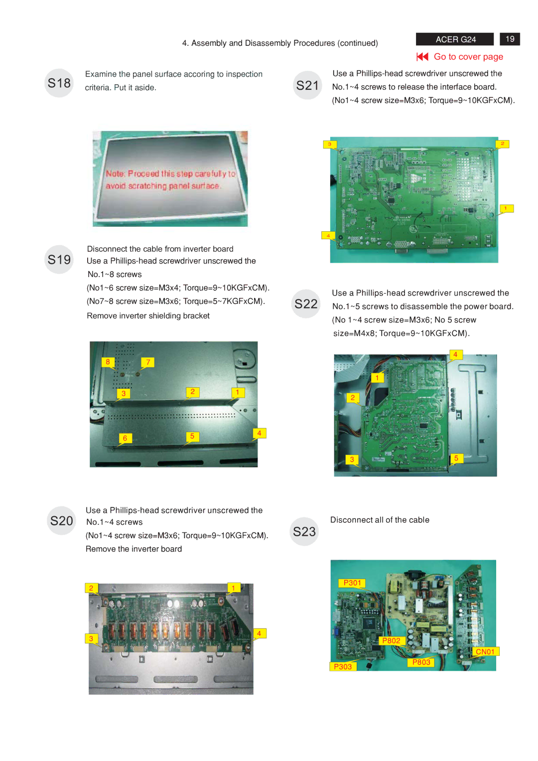
S18 | Examine the panel surface accoring to inspection | Use a | |
criteria. Put it aside. | S21 No.1~4 screws to release the interface board. | ||
(No1~4 screw size=M3x6; Torque=9~10KGFxCM).
3 | 2 |
|
|
|
|
|
| 1 |
|
|
|
|
| 4 |
|
| Disconnect the cable from inverter board |
|
|
|
| |
S19 | Use a |
|
|
| ||
| No.1~8 screws |
|
|
|
|
|
| (No1~6 screw size=M3x4; Torque=9~10KGFxCM). |
| Use a | |||
|
|
|
|
| ||
| (No7~8 screw size=M3x6; Torque=5~7KGFxCM). | S22 | No.1~5 screws to disassemble the power board. | |||
|
|
|
| |||
| Remove inverter shielding bracket |
|
| (No 1~4 screw size=M3x6; No 5 screw | ||
|
|
|
|
| ||
|
|
|
|
| size=M4x8; Torque=9~10KGFxCM). | |
|
|
|
|
|
| 4 |
| 8 | 7 |
|
|
|
|
|
|
|
|
|
| 1 |
| 3 | 2 | 1 |
| 2 |
|
|
|
|
|
|
| |
| 6 | 5 | 4 |
|
|
|
|
|
|
|
| ||
|
|
|
|
|
| |
|
|
|
|
| 3 | 5 |
Use a |
| |
S20 No.1~4 screws |
| Disconnect all of the cable |
(No1~4 screw size=M3x6; Torque=9~10KGFxCM). | S23 | |
Remove the inverter board |
|
|
2 | 1 | P301 |
| ||
4
3 |
| P802 |
|
| |
|
| CN01 |
| P303 | P803 |
|
|
