28
ACER G24
5. Troubleshooting (continued)
Go to cover page
5.9 Checking the DC/DC converter circuit
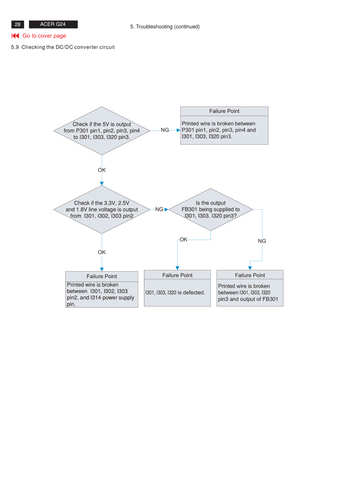
Check if the 5V is output
from P301 pin1, pin2, pin3, pin4
to I301, I303, I320 pin3.
OK
Check if the 3.3V, 2.5V
and 1.8V line voltage is output
from I301, I302, I303 pin2
OK
Failure Point
Printed wire is broken between I301, I302, I303 pin2, and I314 power supply pin.
Failure Point
Printed wire is broken between
NG![]() P301 pin1, pin2, pin3, pin4 and
P301 pin1, pin2, pin3, pin4 and
I301, I303, I320 pin3.
Is the output
NG![]() FB301 being supplied to
FB301 being supplied to
I301, I303, I320 pin3?
OK | NG |
|
Failure Point |
| Failure Point |
|
| Printed wire is broken |
I301, I303, I320 is defected. |
| between I301, I303, I320 |
|
| pin3 and output of FB301 |
|
|
|
