5. Troubleshooting (continued)
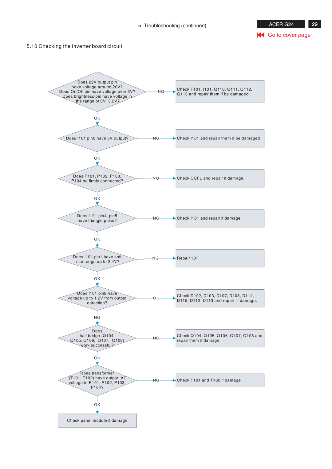
5.10 Checking the inverter board circuit
ACER G24 |
| 29 |
Go to cover page
Does 22V output pin
have voltage around 20V?
Does On/Off pin have voltage over 3V? Does brightness pin have voltage in the range of 0V~3.2V?
OK
Does I101 pin6 have 5V output?
OK
Does P101, P102, P103,
P104 be firmly connected?
OK
Does I101 pin4, pin5 have triangle pulse?
OK
Does I101 pin1 have soft start edge up to 2.4V?
OK
Does I101 pin8 have
voltage up to 1.2V from output
detection?
NG
Does
half bridge (Q104,
Q105, Q106, Q107, Q108)
work successful?
OK
Does transformer (T101, T102) have output AC voltage to P101, P102, P103,
P104?
OK
Check panel module if damage
|
|
| Check F101, I101, Q110, Q111, Q112, |
NG |
|
| |
|
| Q113 and repair them if be damaged | |
|
|
| |
|
|
|
|
NG![]() Check I101 and repair them if be damaged
Check I101 and repair them if be damaged
NG![]() Check CCFL and repair if damage.
Check CCFL and repair if damage.
NG![]() Check I101 and repair if damage
Check I101 and repair if damage
![]() NG
NG![]() Repair 101
Repair 101
|
|
| Check D102, D103, D107, D108, D114, |
OK |
|
| |
|
| D115, D112, D113 and repair if damage. | |
|
|
| |
|
|
|
|
|
|
| Check Q104, Q105, Q106, Q107, Q108 and |
NG |
|
| |
|
| repair them if damage | |
|
|
| |
|
|
|
|
NG![]() Check T101 and T102 if damage
Check T101 and T102 if damage