Manuals
/
Acer
/
Computer Equipment
/
Projector
Acer
X110
service manual
One- Fan Module, Xiii
Models:
X110
1
95
107
107
Download
107 pages
33.95 Kb
92
93
94
95
96
97
98
99
Troubleshooting
Specifications
System Block Diagram for
Connecting the Projector
Dimension
Symptom Procedure
OSD Reset
Setup Procedure VGA
Disassembly & Assembly Process
Firmware Upgrade Procedure
Page 95
Image 95
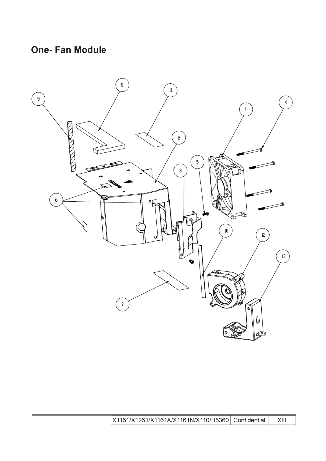
One- Fan Module
X1161/X1261/X1161A/X1161N/X110/H5360
Confidential
XIII
Page 94
Page 96
Page 95
Image 95
Page 94
Page 96
Contents
TSE
X1161/X1261/X1161A/X1161N/X110/H5360
Preface
X1161/X1161A/X1161N/X110/X1261/H5360 Comparison List
Introduction
Table of Content
Disassembly Process & Assembly Process
Function Test & Alignment Procedure
Troubleshooting
Appendix B
Chapter Firmware Upgrade
Chapter Edid Upgrade
Appendix a
Highlight
Introduction
2320 1 Full White with full power / full Black with eco
Segments R90Y35G85C33W42B75 for H5360
TI DMD
For X1161/1161A/X110
Svga
Compatible Mode
VGA
VGA Analog Extended Wide timing
Compatibility Resolution Frequency Hz Frequency KHz
640 x 37.5 43.3 120 61.6 800 x 35.2 37.9
WXGA+
Front /Upper side
Product Overview
Rear side for X1161/X1261/X1161A/X1161N/X110
Rear side for H5360
Remote Control and Control Panel Layout
Freeze
Power
Menu
Resync
Getting Started
Connecting the Projector
System Block Diagram for X1161/X1161A/X110
System Block Diagram for
System Block Diagram for H5360
Bottom Cover Dimension
Equipment Needed & Product Overview
Disassembly & Assembly Process
Disassemble Lamp Module
Disassemble Lamp Cover Module
Disassemble Top Shielding
Disassemble Top Cover Module
Disassemble Front Cover and IR Sensor Board
Disassemble Main Board Module and IO Cover
For X1261/H5360 Black wire tube 2 pin
Disassemble Engine Module
Disassemble DMD Chip DMD Board
Disassemble Color Wheel Module
Disassemble Focus Ring
Disassemble Zoom Ring
Disassemble System Fan Module
Disassemble Lvps Module
Disassemble Blower
Disassemble Lamp Driver Module
Disassemble Bottom Shielding
Disassemble Interrupt Switch
Disassemble Speaker For X1261/H5360
Rod Adjustment
Re-write System Lamp Usage Hour
Assemble Speaker for X1261/H5360
Assemble Bottom Shielding
Assemble Interrupt Switch
Assemble Lamp Driver Module
Assemble Blower
Assemble Lvps Module
Assemble System Fan Module
Assemble Zoom Ring
Assemble Focus Ring
Assemble Color Wheel Module
Assemble DMD Chip DMD Board
Assemble IO Cover Main Board Module
Assemble Engine Module
X1161/X1261/X1161A/X1161N/X110/H5360 Confidential
Assemble IR Sensor Board and Front Cover
Assemble Top Cover Moudle
Assemble Top Shielding
Assemble Lamp Cover Module
Assemble Lamp Moudle
LED Lighting Message
Message Power LED Red Blue
Symptom Procedure
Main Procedure
Ensure the Signal Cable and Source work
Ensure the projection screen without dirt
An unique Universal Password which is printed on
Test Equipment Needed
Service Mode
OSD Reset
NFF
Test Condition
Edid
Defect specification table
Test Inspection Procedure
Bright Pixel
Frequency and tracking boundary
Dark Blemish
Dark Pixel
Bright Blemish
Color performance
Focus test
Video Calibration
Calibration
PC Calibration
Sensor Calibration
Audio Test for X1261/H5360
Video Performance
Video for X1161/X1161A/X110/X1261/H5360
HDTV/ Component
Test equipment
Optical Performance Measure
Hdmi Test for H5360
Uniformity
Brightness
Full On/Full Off Contrast
DDC
Others
Function Inspection
Check points for exterior and print pattern
Hardware
Equipment Needed
DLP Composer Lite Setup Procedure
X1161/X1261/X1161A/X1161N/X110/H5360 Confidential
USB Driver Upgrade Procedure for X1161A/X1161N/X110
Firmware Upgrade Procedure
For X1261/H5360
Page
Waveform Download
Edid Introduction
Edid Upgrade
Software
Setup Procedure VGA
Edid Key-In Procedure
X1161/X1261/X1161A/X1161N/X110/H5360 Confidential
Un-lock Snid and Default Language Reset
Appendix a Exploded Image
Front Module
Assy Lamp Cover Module X1161 Service
70.8CP07G001 FAN Shielding Module
IO Module
III
70.8CQ01G001
X1161/X1261/X1161A/X1161N/X110/H5360 Confidential
52.88N07G001 Adjustable Foot RUBBER,EP721
Assy Bottom Cover Module Service
Front Module
Viii
IO Module
Label IO
Assy Main Board Module X1161 Service
61.8CP10G001 Main Shielding Small Tinplate
Pcba Main Board for
IO Module
Label IO Base
Assy Main Board Module X1261 Service
Assy IO Cover Module X1261 Service
61.8CP09G001 Main Shielding Tinplate
XII
Bottom Shielding Module
61.8CP06G001 Bottom Shielding Secc
Xiii
One- Fan Module
XIV
52.88T01G001 FAN Shelding Front AIR Tight CVS
Blower FAN
Focus Ring MN3600H
Engine Module
Assy Optical Engine Module Z15 S450
XVI
Assy Engine Module
70.8CP10G001 Assy Engine Bottom Cover Z15
Assy Engine Module X1161 Service
Assy Engine Module X1261 Service
Pcba DMD Board for
Pcba Photo Sensor Board for
70.8CP21GR01 Assy Color Wheel Module X1161 Service
Assy Color Wheel Module Z15
CW Bracket Secc
Assy Lamp Driver Module
X1161/X1261/X1161A/X1161N/X110/H5360 Confidential
PE BAG Zipper #9 W/RECYCLING Mark for
Cable Power Cord 1.8M SP-60/IS-14 UK DIS
Cable Power Cord 1.8M SP-023/IS-14 EU
Rope DIS-WARNING Label
Serial Number Format for Projector take X1261 for example
Serial Number System Definition
915 00000
Vendor Code Firmware Version MB version Date Code
II. Pcba Code Definition
Pcba Code for Projector
General command type Projector receives commands
RS232 function command summary table for X1261/H5360
Top
Page
Image
Contents