2-7 Disassemble Main Board
Module and IO Cover
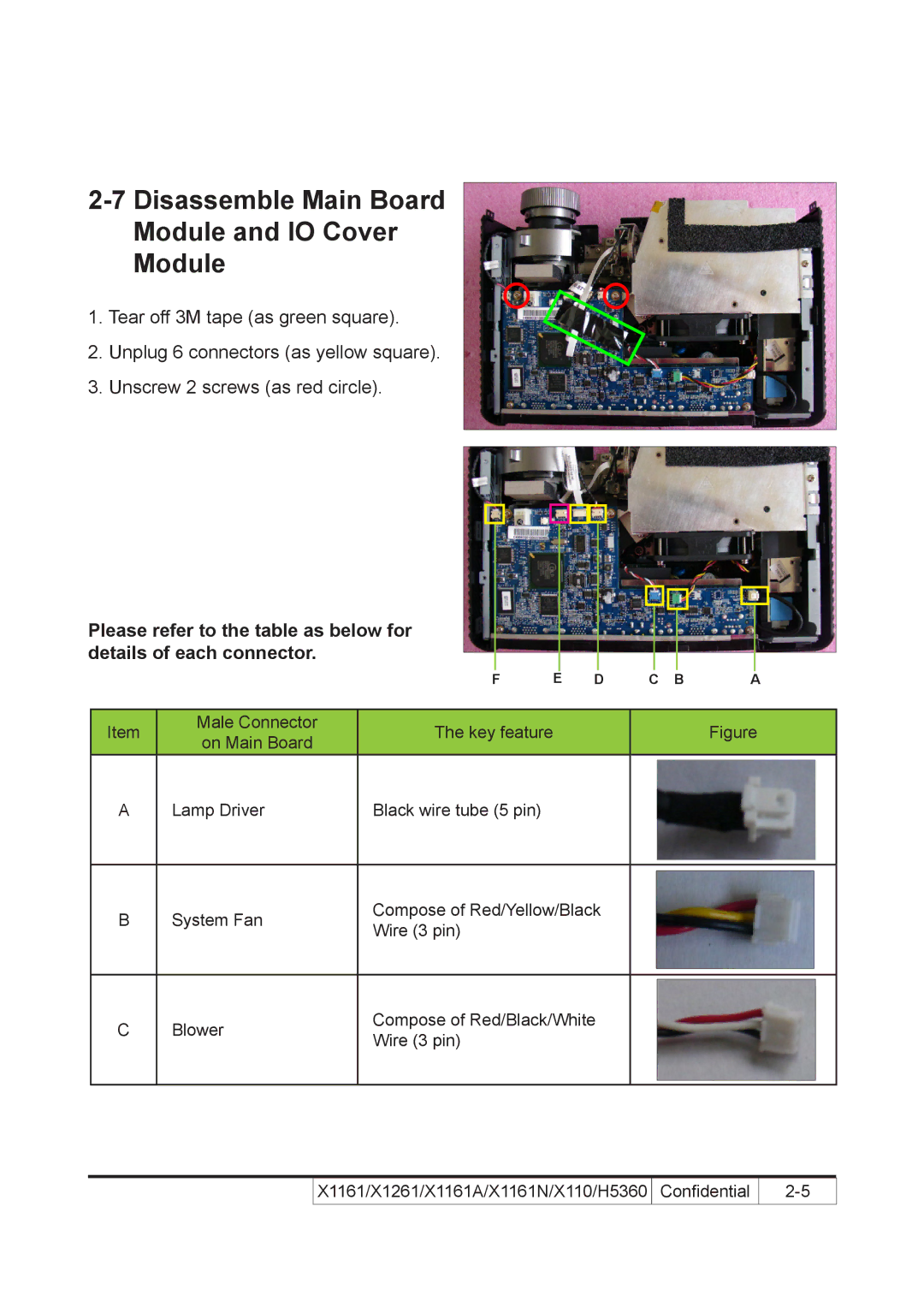
Module
1.Tear off 3M tape (as green square).
2.Unplug 6 connectors (as yellow square).
3.Unscrew 2 screws (as red circle).
Please refer to the table as below for details of each connector.
|
| F | E | D | C B | A |
|
|
|
|
|
|
|
Item | Male Connector | The key feature |
|
| Figure | |
on Main Board |
|
| ||||
|
|
|
|
|
| |
A | Lamp Driver | Black wire tube (5 pin) |
|
|
|
|
B | System Fan | Compose of Red/Yellow/Black | |
Wire (3 pin) | |||
|
|
C | Blower | Compose of Red/Black/White | |
Wire (3 pin) | |||
|
|
| X1161/X1261/X1161A/X1161N/X110/H5360 | Confidential | 2- |