| 758 | 110 |
|
| ||
| 683 | 100 |
|
| ||
(KILOPASCALS)PRESSURELINESUCTION | OUTDOOR TEMP | |||||
| (PSIG)PRESSURELINESUCTION |
| ||||
|
| OF | OC | |||
|
|
|
| 115 | 46 | |
| 621 |
| 90 | 105 | 41 | |
|
|
|
| 95 | 35 | |
| 552 |
| 80 | 85 | 29 | |
|
|
|
| 75 | 24 | |
| 483 |
| 70 | 65 | 18 | |
|
|
|
| |||
|
|
|
| 55 | 13 | |
| 414 |
| 60 | 45 | 7 | |
|
|
|
| |||
| 345 |
| 50 |
|
| |
| 276 |
| 40 |
|
| |
| 207 |
| 30 |
|
| |
30 | 40 | 50 | 60 | 70 | 80 | 90 |
| SUCTION LINE TEMPERATURE (OF) |
| ||||
4 | 10 | 16 | 21 | 27 | 32 | |
| SUCTION LINE TEMPERATURE (OC) |
| ||||
C00164
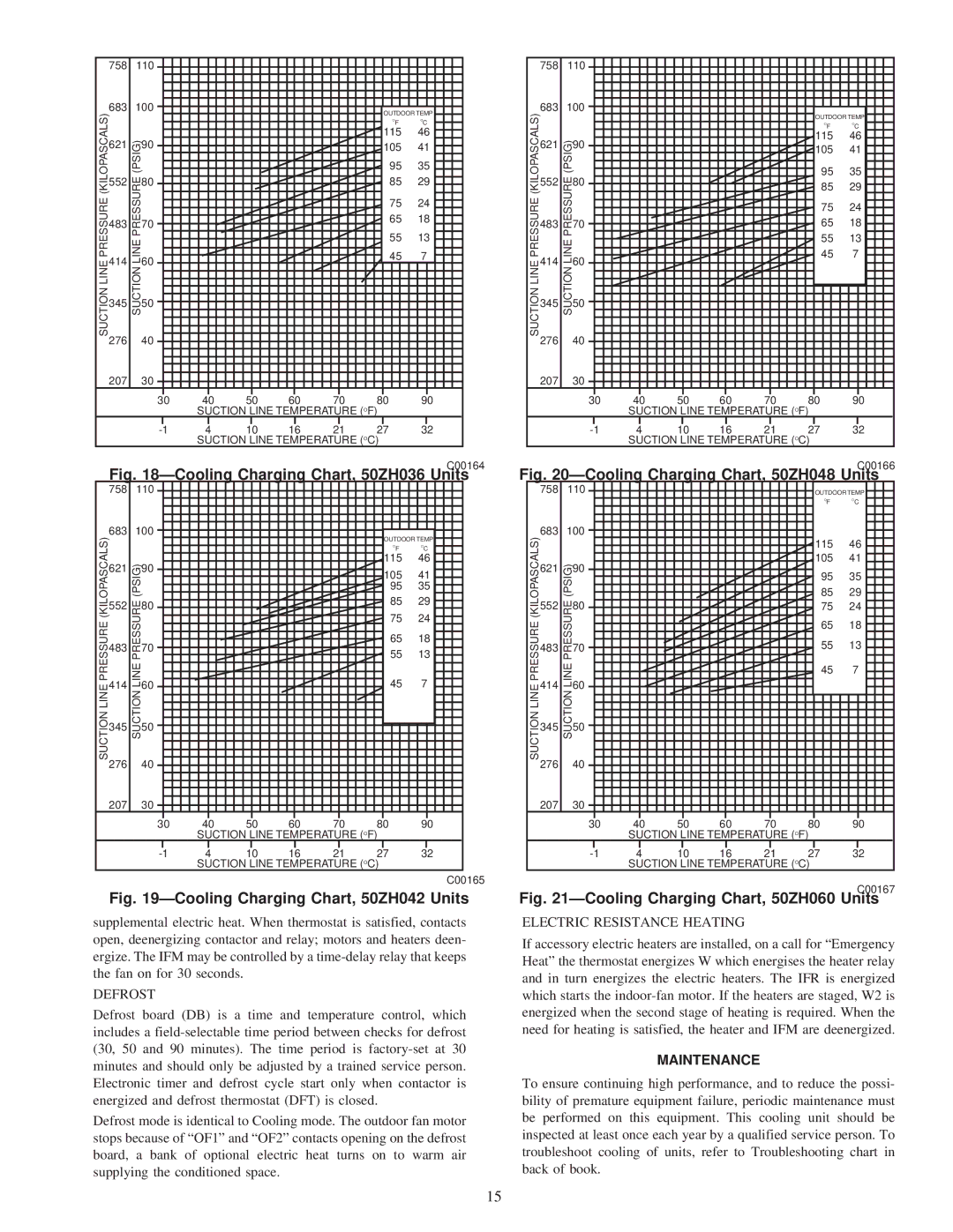
Fig. 18ÐCooling Charging Chart, 50ZH036 Units
758110
683100
(KILOPASCALS)PRESSURELINESUCTION |
| (PSIG)PRESSURELINESUCTION |
| OUTDOOR TEMP | |
|
| OF | OC | ||
| 621 |
| 90 | 115 | 46 |
|
| 105 | 41 | ||
|
|
|
| ||
|
|
|
| 95 | 35 |
| 552 |
| 80 | 85 | 29 |
|
|
|
| ||
|
|
|
| 75 | 24 |
| 483 |
| 70 | 65 | 18 |
|
| 55 | 13 | ||
|
|
|
| ||
| 414 |
| 60 | 45 | 7 |
| 345 |
| 50 |
|
|
|
|
|
| ||
| 276 |
| 40 |
|
|
| 207 |
| 30 |
|
|
30 | 40 | 50 | 60 | 70 | 80 | 90 |
| SUCTION LINE TEMPERATURE (OF) |
| ||||
4 | 10 | 16 | 21 | 27 | 32 | |
| SUCTION LINE TEMPERATURE (OC) |
| ||||
C00165
Fig. 19ÐCooling Charging Chart, 50ZH042 Units
supplemental electric heat. When thermostat is satisfied, contacts open, deenergizing contactor and relay; motors and heaters deen- ergize. The IFM may be controlled by a
DEFROST
Defrost board (DB) is a time and temperature control, which includes a
Defrost mode is identical to Cooling mode. The outdoor fan motor stops because of ªOF1º and ªOF2º contacts opening on the defrost board, a bank of optional electric heat turns on to warm air supplying the conditioned space.
| 758 | 110 |
|
|
|
|
|
| |
SUCTION LINE PRESSURE (KILOPASCALS) | 683 | 100 |
|
|
|
|
|
| |
|
|
|
|
|
|
| OUTDOOR TEMP | ||
|
|
|
|
|
|
| OF | OC | |
621 | SUCTION LINE PRESSURE (PSIG) | 90 |
|
|
|
| 115 | 46 | |
|
|
|
| 105 | 41 | ||||
|
|
|
|
|
| ||||
552 | 80 |
|
|
|
| 95 | 35 | ||
|
|
|
| 85 | 29 | ||||
|
|
|
|
|
| ||||
|
|
|
|
|
| 75 | 24 | ||
483 | 70 |
|
|
|
| 65 | 18 | ||
|
|
|
|
|
| 55 | 13 | ||
414 | 60 |
|
|
|
| 45 | 7 | ||
|
|
|
|
|
| ||||
345 | 50 |
|
|
|
|
|
| ||
276 | 40 |
|
|
|
|
|
| ||
|
|
|
|
|
|
|
| ||
| 207 |
| 30 |
|
|
|
|
|
|
|
|
| 30 | 40 | 50 | 60 | 70 | 80 | 90 |
SUCTION LINE TEMPERATURE (OF)
4 | 10 | 16 | 21 | 27 | 32 | |
| SUCTION LINE TEMPERATURE (OC) |
| ||||
C00166
Fig. 20ÐCooling Charging Chart, 50ZH048 Units
| 758 | 110 |
|
|
|
| OUTDOOR TEMP | ||
|
|
|
|
|
|
|
| OF | OC |
SUCTION LINE PRESSURE (KILOPASCALS) | 683 | 100 |
|
|
|
|
|
| |
|
|
|
|
|
|
| 115 | 46 | |
621 | SUCTION LINE PRESSURE (PSIG) | 90 |
|
|
|
| 105 | 41 | |
|
|
|
| 95 | 35 | ||||
|
|
|
|
|
| ||||
|
|
|
|
|
| 85 | 29 | ||
552 | 80 |
|
|
|
| 75 | 24 | ||
|
|
|
|
|
| 65 | 18 | ||
483 | 70 |
|
|
|
| 55 | 13 | ||
|
|
|
|
|
| 45 | 7 | ||
414 | 60 |
|
|
|
|
|
| ||
345 | 50 |
|
|
|
|
|
| ||
276 | 40 |
|
|
|
|
|
| ||
|
|
|
|
|
|
|
| ||
| 207 |
| 30 |
|
|
|
|
|
|
|
|
| 30 | 40 | 50 | 60 | 70 | 80 | 90 |
SUCTION LINE TEMPERATURE (OF)
4 | 10 | 16 | 21 | 27 | 32 | |
| SUCTION LINE TEMPERATURE (OC) |
| ||||
C00167
Fig. 21ÐCooling Charging Chart, 50ZH060 Units
ELECTRIC RESISTANCE HEATING
If accessory electric heaters are installed, on a call for ªEmergency Heatº the thermostat energizes W which energises the heater relay and in turn energizes the electric heaters. The IFR is energized which starts the
MAINTENANCE
To ensure continuing high performance, and to reduce the possi- bility of premature equipment failure, periodic maintenance must be performed on this equipment. This cooling unit should be inspected at least once each year by a qualified service person. To troubleshoot cooling of units, refer to Troubleshooting chart in back of book.
15