4.Connect the RED lead to the BLK wire from which the ORG lead was disconnected. Insulate with wirenut from Step 1.
5.Using the wirenut removed from the RED lead, insulate the loose terminal on the ORG lead.
6.Wrap the wirenuts with electrical tape so that the metal terminals cannot be seen.
Indoor
PRE-START-UP
Failure to observe the following warnings could result in serious injury or death:
1.Follow recognized safety practices and wear protective goggles when checking or servicing refrigerant system.
2.Do not operate compressor or provide any electric power to unit unless compressor terminal cover is in place and secured.
3.Do not remove compressor terminal cover until all electri- cal sources are disconnected and lockout tag is installed.
4.Relieve all pressure from both high- and
5.Never attempt to repair soldered connection while refrig- erant system is under pressure.
6.Do not use torch to remove any component. System contains oil and refrigerant under pressure. To remove a component, wear protective goggles and proceed as fol- lows:
a.Shut off electrical power to unit and install lockout tag.
b.Relieve all refrigerant from system using both high- and
c.Cut component connecting tubing with tubing cutter and remove component from unit.
d.Carefully unsweat remaining tubing stubs when neces- sary. Oil can ignite when exposed to torch flame.
Use the
1.Remove all access panels.
2.Read and follow instructions on all DANGER, WARNING, CAUTION, and INFORMATION labels attached to, or shipped with, unit.
Make the following inspections:
a.Inspect for shipping and handling damages such as broken lines, loose parts, disconnected wires, etc.
b.Inspect for oil at all refrigerant tubing connections and on unit base. Detecting oil generally indicates a refrigerant leak.
c.Inspect all field- and
d.Inspect coil fins. If damaged during shipping and handling, carefully straighten fins with a fin comb.
3.Verify the following conditions:
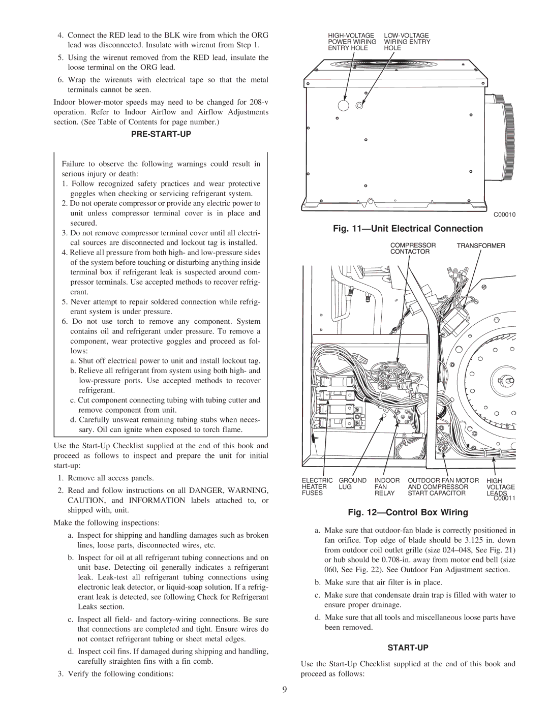
POWER WIRING | WIRING ENTRY |
ENTRY HOLE | HOLE |
C00010
Fig. 11ÐUnit Electrical Connection
ELECTRIC | GROUND | INDOOR | OUTDOOR FAN MOTOR | HIGH |
HEATER | LUG | FAN | AND COMPRESSOR | VOLTAGE |
FUSES |
| RELAY | START CAPACITOR | LEADS |
|
|
|
| C00011 |
Fig. 12ÐControl Box Wiring
a.Make sure that
b.Make sure that air filter is in place.
c.Make sure that condensate drain trap is filled with water to ensure proper drainage.
d.Make sure that all tools and miscellaneous loose parts have been removed.
START-UP
Use the
9