OUTDOOR COIL
ACCUMULATOR | COMPRESSOR |
| A |
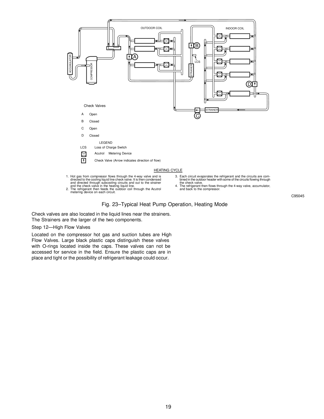
Check Valves
AOpen
BClosed
COpen
DClosed
LEGEND
LCS Loss of Charge Switch
Acutrol Metering Device
Check Valve (Arrow indicates direction of flow)
INDOOR COIL
B
LCS
STRAINER
D
STRAINER
C
HEATING CYCLE
1.Hot gas from compressor flows through the
2.The refrigerant then feeds the outdoor coil through the Acutrol metering device on each circuit.
3.Each circuit evaporates the refrigerant and the circuits are com- bined in the outdoor header with some of the circuits flowing through the check valve.
4.The refrigerant then flows through the
C95045
Fig. 23±Typical Heat Pump Operation, Heating Mode
Check valves are also located in the liquid lines near the strainers.
The Strainers are the larger of the two components.
Step 12ÐHigh Flow Valves
Located on the compressor hot gas and suction tubes are High Flow Valves. Large black plastic caps distinguish these valves with
19