|
| LEGEND |
|
FLA | — | Full Load Amps |
|
LRA | — | Locked Rotor Amps | ® |
MCA | — | Minimum Circuit Amps |
|
MOCP — Maximum Overcurrent Protection |
| ||
RLA | — | Rated Load Amps |
|
CKT BKR — Circuit Breaker |
| ||
NOTES:
1.In compliance with NEC (National Electrical Code) requirements for multimotor and combination load equipment (refer to NEC Articles 430 and 440), the overcurrent protective device for the unit shall be Power Supply fuse . Canadian units may be fuse or circuit breaker.
2.Minimum wire size is based on 60 C copper wire. If other than 60 C wire is used, or if length exceeds wire length in table, determine size from NEC.
3.Unbalanced
Never operate a motor where a phase imbalance in supply volt- age is greater than 2%. Use the following formula to determine the percentage of voltage imbalance.
%Voltage imbalance
=100 x max voltage deviation from average voltage average voltage
758110
683100
(KILOPASCALS)PRESSURELINESUCTION |
| (PSIG)PRESSURELINESUCTION |
| OUTDOOR TEMP | |
|
| OF | OC | ||
|
|
|
| ||
| 621 |
| 90 | 115 | 46 |
|
|
|
| 105 | 41 |
|
|
|
| 95 | 35 |
| 552 |
| 80 | 85 | 29 |
|
| 75 | 24 | ||
|
|
|
| ||
|
|
|
| 65 | 18 |
|
|
|
| 55 | 13 |
| 483 |
| 70 | 45 | 7 |
|
|
|
| ||
| 414 |
| 60 |
|
|
| 345 |
| 50 |
|
|
| 276 |
| 40 |
|
|
| 207 |
| 30 |
|
|
30 | 40 | 50 | 60 | 70 | 80 | 90 |
| SUCTION LINE TEMPERATURE (OF) |
| ||||
4 | 10 | 16 | 21 | 27 | 32 | |
| SUCTION LINE TEMPERATURE (OC) |
| ||||
C00162
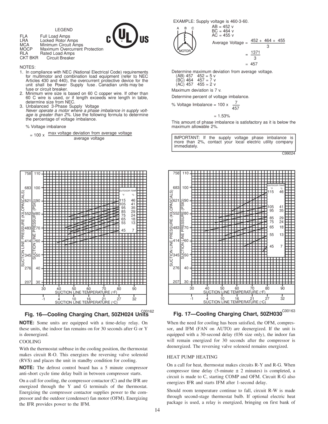
Fig. 16ÐCooling Charging Chart, 50ZH024 Units
NOTE: Some units are equipped with a
COOLING
With the thermostat subbase in the cooling position, the thermostat makes circuit
NOTE: The defrost control board has a 5 minute compressor
On a call for cooling, the compressor contactor (C) and the IFR are energized through the Y and G terminals of the thermostat. Energizing the compressor contactor supplies power to the com- pressor and the outdoor (condenser) fan motor (OFM). Energizing the IFR provides power to the IFM.
EXAMPLE: Supply voltage is
AB = 452 v BC = 464 v AC = 455 v
Average Voltage = 452 + 464 + 455 3
= 1371
3 = 457
Determine maximum deviation from average voltage. (AB) 457 452 = 5 v
(BC) 464 457 = 7 v (AC) 457 455 = 2 v
Maximum deviation is 7 v.
Determine percent of voltage imbalance.
% Voltage Imbalance = 100 x |
| 7 | |
457 | |||
| |||
= 1.53%
This amount of phase imbalance is satisfactory as it is below the maximum allowable 2%.
IMPORTANT: If the supply voltage phase imbalance is more than 2%, contact your local electric utility company immediately.
|
|
|
|
|
|
|
|
| C99024 |
| 758 | 110 |
|
|
|
|
|
| |
| 683 | 100 |
|
|
|
| OUTDOOR TEMP | ||
SUCTION LINE PRESSURE (KILOPASCALS) |
|
|
|
| OF | OC | |||
|
|
|
|
|
|
| 115 | 46 | |
621 | SUCTION LINE PRESSURE (PSIG) | 90 |
|
|
|
|
|
| |
|
|
|
|
|
| 105 | 41 | ||
552 | 80 |
|
|
|
| 95 | 35 | ||
|
|
|
|
|
| ||||
|
|
|
|
|
| 85 | 29 | ||
|
|
|
|
|
| 75 | 24 | ||
483 | 70 |
|
|
|
| 65 | 18 | ||
|
|
|
|
|
| 55 | 13 | ||
414 | 60 |
|
|
|
|
|
| ||
|
|
|
|
|
| 45 | 7 | ||
345 | 50 |
|
|
|
|
|
| ||
276 | 40 |
|
|
|
|
|
| ||
|
|
|
|
|
|
|
| ||
| 207 |
| 30 |
|
|
|
|
|
|
|
|
| 30 | 40 | 50 | 60 | 70 | 80 | 90 |
SUCTION LINE TEMPERATURE (OF)
4 | 10 | 16 | 21 | 27 | 32 | |
| SUCTION LINE TEMPERATURE (OC) |
| ||||
Fig. 17ÐCooling Charging Chart, 50ZH030C00163
When the need for cooling has been satisfied, the OFM, compres- sor, and IFM (FAN on AUTO) are deenergized. If the unit is equipped with a
HEAT PUMP HEATING
On a call for heat, thermostat makes circuits
Should room temperature continue to fall, circuit
14