Checkpoints
A checkpoint is either a byte or word value output to I/O port 80h. The BIOS outputs checkpoints throughout bootblock and
Viewing BIOS checkpoints
Viewing all checkpoints generated by the BIOS requires a checkpoint card, also referred to as a POST card or POST diagnostic card. These are ISA or PCI
Bootblock Initialization Code Checkpoints
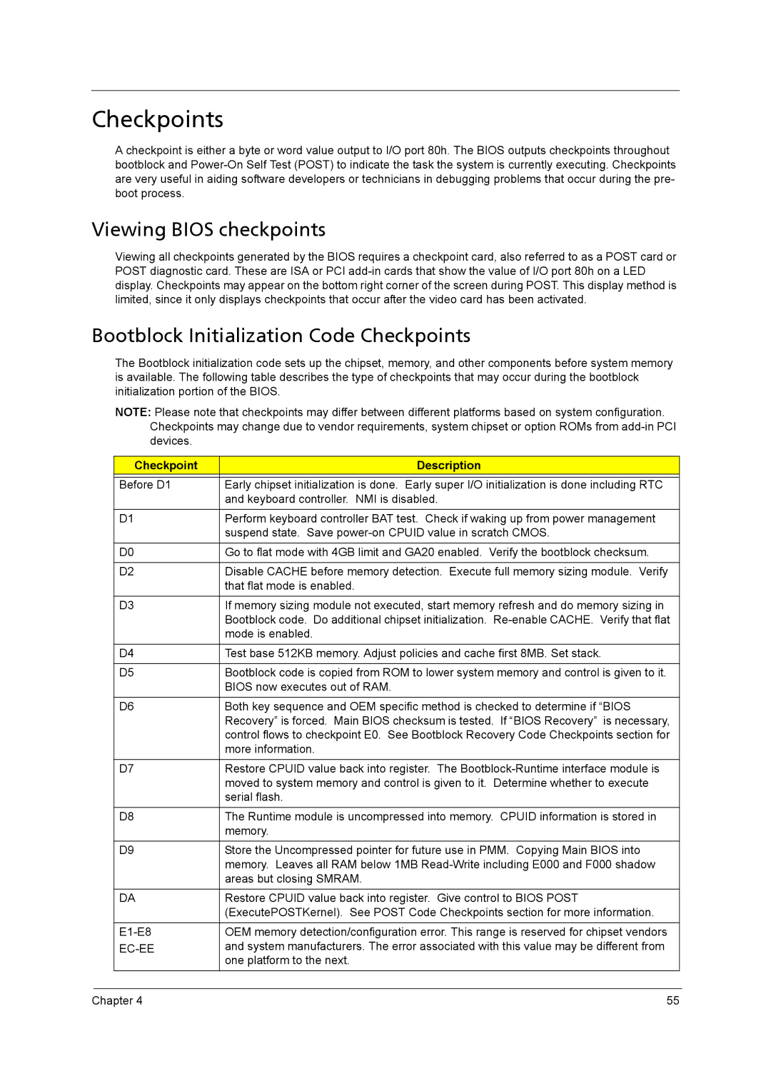
The Bootblock initialization code sets up the chipset, memory, and other components before system memory is available. The following table describes the type of checkpoints that may occur during the bootblock initialization portion of the BIOS.
NOTE: Please note that checkpoints may differ between different platforms based on system configuration. Checkpoints may change due to vendor requirements, system chipset or option ROMs from
Checkpoint | Description |
|
|
Before D1 | Early chipset initialization is done. Early super I/O initialization is done including RTC |
| and keyboard controller. NMI is disabled. |
|
|
D1 | Perform keyboard controller BAT test. Check if waking up from power management |
| suspend state. Save |
|
|
D0 | Go to flat mode with 4GB limit and GA20 enabled. Verify the bootblock checksum. |
|
|
D2 | Disable CACHE before memory detection. Execute full memory sizing module. Verify |
| that flat mode is enabled. |
|
|
D3 | If memory sizing module not executed, start memory refresh and do memory sizing in |
| Bootblock code. Do additional chipset initialization. |
| mode is enabled. |
|
|
D4 | Test base 512KB memory. Adjust policies and cache first 8MB. Set stack. |
|
|
D5 | Bootblock code is copied from ROM to lower system memory and control is given to it. |
| BIOS now executes out of RAM. |
|
|
D6 | Both key sequence and OEM specific method is checked to determine if “BIOS |
| Recovery” is forced. Main BIOS checksum is tested. If “BIOS Recovery” is necessary, |
| control flows to checkpoint E0. See Bootblock Recovery Code Checkpoints section for |
| more information. |
|
|
D7 | Restore CPUID value back into register. The |
| moved to system memory and control is given to it. Determine whether to execute |
| serial flash. |
|
|
D8 | The Runtime module is uncompressed into memory. CPUID information is stored in |
| memory. |
|
|
D9 | Store the Uncompressed pointer for future use in PMM. Copying Main BIOS into |
| memory. Leaves all RAM below 1MB |
| areas but closing SMRAM. |
|
|
DA | Restore CPUID value back into register. Give control to BIOS POST |
| (ExecutePOSTKernel). See POST Code Checkpoints section for more information. |
|
|
OEM memory detection/configuration error. This range is reserved for chipset vendors | |
| and system manufacturers. The error associated with this value may be different from |
| one platform to the next. |
Chapter 4 | 55 |