SECTION IV
DESCRIPTION OF PARTS
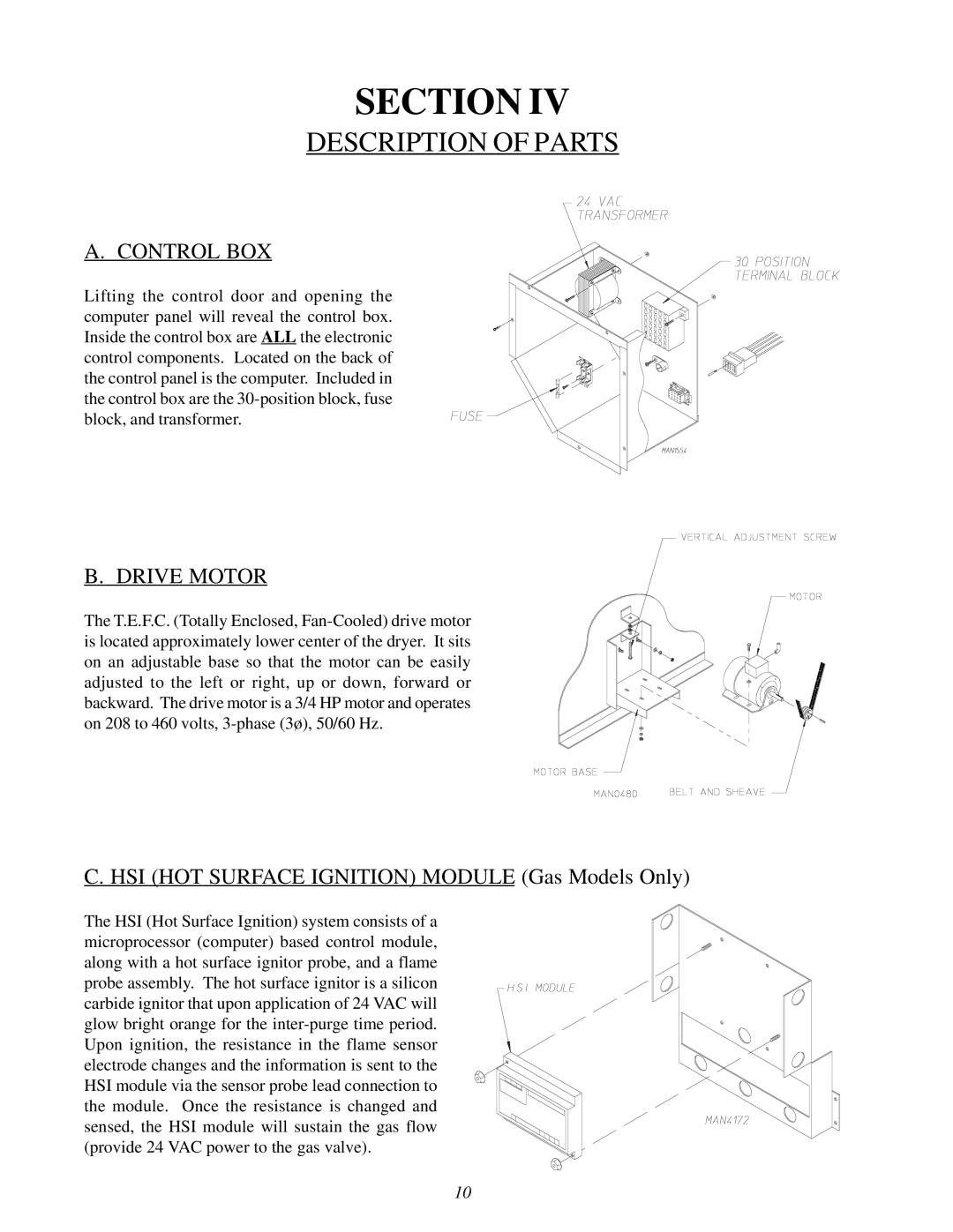
A. CONTROL BOX
Lifting the control door and opening the computer panel will reveal the control box. Inside the control box are ALL the electronic control components. Located on the back of the control panel is the computer. Included in the control box are the
B. DRIVE MOTOR
The T.E.F.C. (Totally Enclosed,
C. HSI (HOT SURFACE IGNITION) MODULE (Gas Models Only)
The HSI (Hot Surface Ignition) system consists of a microprocessor (computer) based control module, along with a hot surface ignitor probe, and a flame probe assembly. The hot surface ignitor is a silicon carbide ignitor that upon application of 24 VAC will glow bright orange for the
10