NOTE: Before reestablishing electrical power to the dryer visually check the following (refer to illustration above).
5. Reestablish procedure for installation of new ignitor.
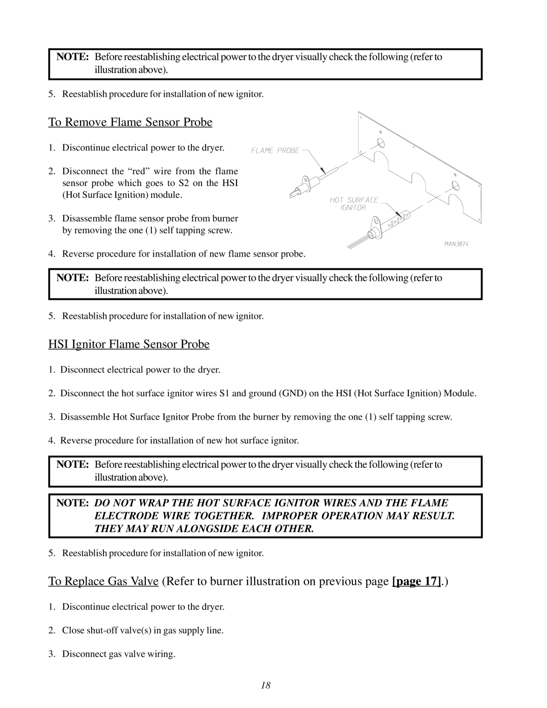
To Remove Flame Sensor Probe
1. Discontinue electrical power to the dryer.
2. Disconnect the “red” wire from the flame sensor probe which goes to S2 on the HSI (Hot Surface Ignition) module.
3. Disassemble flame sensor probe from burner by removing the one (1) self tapping screw.
4. Reverse procedure for installation of new flame sensor probe.
NOTE: Before reestablishing electrical power to the dryer visually check the following (refer to illustration above).
5. Reestablish procedure for installation of new ignitor.
HSI Ignitor Flame Sensor Probe
1.Disconnect electrical power to the dryer.
2.Disconnect the hot surface ignitor wires S1 and ground (GND) on the HSI (Hot Surface Ignition) Module.
3.Disassemble Hot Surface Ignitor Probe from the burner by removing the one (1) self tapping screw.
4.Reverse procedure for installation of new hot surface ignitor.
NOTE: Before reestablishing electrical power to the dryer visually check the following (refer to illustration above).
NOTE: DO NOT WRAP THE HOT SURFACE IGNITOR WIRES AND THE FLAME ELECTRODE WIRE TOGETHER. IMPROPER OPERATION MAY RESULT. THEY MAY RUN ALONGSIDE EACH OTHER.
5. Reestablish procedure for installation of new ignitor.
To Replace Gas Valve (Refer to burner illustration on previous page [page 17].)
1.Discontinue electrical power to the dryer.
2.Close
3.Disconnect gas valve wiring.
18