Manuals
/
ADC
/
Video Game
/
Keyboard
ADC
450428
service manual
Models:
450428
1
53
62
62
Download
62 pages
42.77 Kb
50
51
52
53
54
55
56
57
Troubleshooting
Install
E.D. Display Indicator Number
Maintenance
Manual Reset Thermostat
Phase 6 OPL System Diagnostics
GAS Burner Assembly
Adjustments
For Phase 6 Models
How to
Page 53
Image 53
49
Page 52
Page 54
Page 53
Image 53
Page 52
Page 54
Contents
American Dryer Corporation
ML-130
Retain This Manual In a Safe Place For Future Reference
For Your Safety
Page
Table of Content
Phase 6 OPL System Diagnostics
Important Information
Safety Precautions
Standards
MATERIALS, GASOLINE, and Their Flammable Vapors
Routine Maintenance
Cleaning
Lubrication
Adjustments
Electrical and GAS Requirements
Installation Requirements
ENCLOSURE, AIR SUPPLY, and Exhaust Requirements
Operational Service Check Procedure
Page
Control BOX
Description of Parts
Drive Motor
HSI HOT Surface Ignition Module Gas Models Only
Blower Motor and Impellor
GAS Burner Assembly
Idler Assembly
Tumbler Basket
Main Door Switch
Tumbler Basket Bearing and Pulley Arrangement
HI-LIMIT Gas and Electric Models Only
Sail Switch Gas and Electric Models Only
Manual Reset Thermostat
Steam Damper System
Lint Drawer Switch
Lint Drawer
Introduction
Servicing
Computer Controls
To Replace Computer Control Panel
To Replace Computer
To Replace Keyboard Touchpad Label Assembly
To Replace Microprocessor Temperature Sensor Probe
To Remove Hot Surface Ignitor refer to illustration above
Ignition Controls
HSI Ignitor Flame Sensor Probe
To Remove Flame Sensor Probe
To Replace Main Burner Orifices
To Test and Adjust Gas Water Column Pressure
To Convert from Natural Gas to L.P. Gas
Thermostats
To Replace Burner Tubes
To Replace HSI Hot Surface Ignition Module
Page
To Replace Sail Switch
Sail Switch Assembly Gas and Electric Models Only
To Adjust Sail Switch
Personal Injury or Fire could Result
To Install New Main Door Glass
To Replace Main Door Assembly
To Replace Main Door Hinge Block
To Replace Front Panel
To Replace Small Idler Pulley
Pulleys
To Replace Tumbler Basket Pulley
To Replace Motor Pulley
To Replace Large Idler Pulley
Tumbler Basket Alignment Vertical Up and Down Adjustment
Tumbler Basket Assembly
To Replace Tumbler Basket or Tumbler Basket Support
Tumbler Basket Alignment Lateral Side to Side Adjustment
To Replace Front Tumbler Basket Support Pillow Block Bearing
To Replace Rear Idler Shaft Pillow Block Bearing
To Replace Front Idler Shaft Pillow Block Bearing
Belt Tension Adjustment Motor to Idler
Belt Tension Adjustment Tumbler Basket to Idler
Belts
To Replace V-Belts
To Replace Impellor Motor Fan Shaft Drive
Motors
To Replace Drive Motor
Impellor
Lint Drawer Assembly To Replace Lint Screen
To Replace Lint Drawer Switch
Computer will not accept keyboard touchpad entries
Troubleshooting
No display on computer
Dryer operates but is taking too long to dry
Dryer will not start, but computer display indicators are on
Overload for impellor fan motor is tripping
Burner hi-limit safety thermostat is tripping
Thermal overload for drive motor is tripping
There is excessive vibration coming from the tumbler basket
Diagnostic L.E.D. light emitting diode Display Failure Codes
Phase 6 OPL System Diagnostics
Page
E.D. Display Indicator Number
E.D. light emitting diode Display Indicators
E.D. Display Indicator Number
HT1 Heat Output L.E.D. Indicator
FAN Blower Output L.E.D. Indicator
AIR AIR JET Output L.E.D. Indicator Optional
Main Main Door Input L.E.D. Indicator
Fuse Main Fuse Input L.E.D. Indicator
Lint Lint Door Input L.E.D. Indicator
Power Supply Input L.E.D. Indicator
Flame bURNER Control Fail Input L.E.D. Indicator
ALL REV
E.D. Codes 1. Display Codes
GAS only Ignition Attempt Failure
GAS Models only Power 24 VAC is not Evident AT GAS Valve
GAS/ELECTRIC only BURNER/OVEN Open HI-LIMIT Circuit
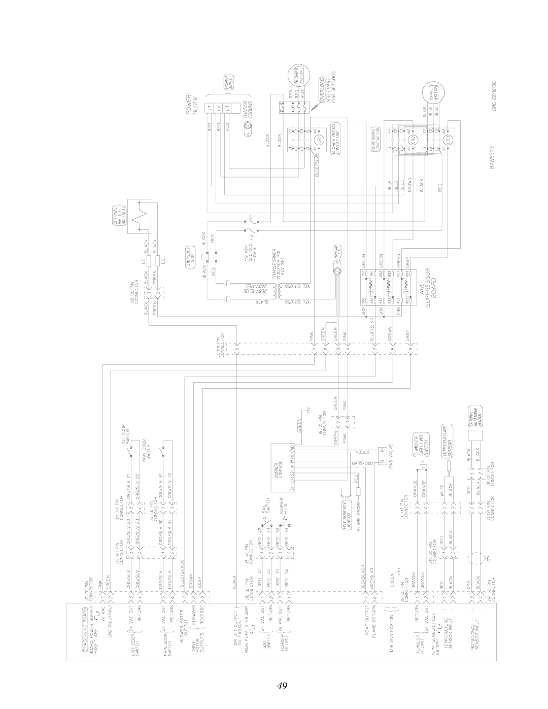
Computer Logic and Wiring Diagram
Page
Drive motor reverses but does not forward, blower motor runs
No Display Condition
Lint Door Condition
Blower motor does not operate, drive motor runs
Microprocessor Computer
Main Door Condition
For Phase 6 Models
Manual Reset HI-LIMIT Instructions
Motor Plate High and LOW Voltage
Technical Information
Information on the Data Label
Data Label
HOW to USE a Manometer
Tool List
ADC450428 1- 02/22/00-25
Top
Page
Image
Contents