7.Tighten cap screws progressively. There should remain a gap between the sheave hub and the flange of the bushing.
IMPORTANT: Tighten screws evenly and progressively. Never allow the sheave to be drawn in contact with the flange of the bushing. This gap should measure from 1/8” to 1/4”. Proper cap screw torque is 6
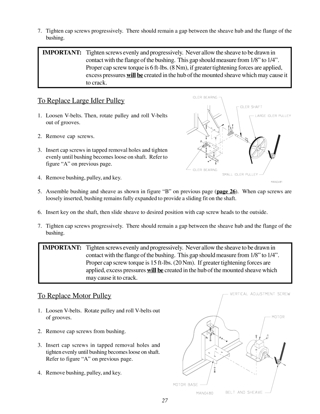
To Replace Large Idler Pulley
1.Loosen
2. Remove cap screws.
3. Insert cap screws in tapped removal holes and tighten evenly until bushing becomes loose on shaft. Refer to figure “A” on previous page.
4.Remove bushing, pulley, and key.
5.Assemble bushing and sheave as shown in figure “B” on previous page (page 26). When cap screws are loosely inserted, bushing remains fully expanded to provide a sliding fit on the shaft.
6.Insert key on the shaft, then slide sheave to desired position with cap screw heads to the outside.
7.Tighten cap screws progressively. There should remain a gap between the sheave hub and the flange of the bushing.
IMPORTANT: Tighten screws evenly and progressively. Never allow the sheave to be drawn in contact with the flange of the bushing. This gap should measure from 1/8” to 1/4”. Proper cap screw torque is 15
To Replace Motor Pulley
1.Loosen
2. Remove cap screws from bushing.
3. Insert cap screws in tapped removal holes and tighten evenly until bushing becomes loose on shaft. Refer to figure “A” on previous page.
4. Remove bushing, pulley, and key.
27