b. Loosen the two (2) Phillips head screws securing bracket assembly to dryer and remove bracket from dryer.
NOTE: DO NOT remove screws.
4. Disassemble sensor probe from bracket assembly by removing the top
5.Disconnect the two (2) “orange” wires from the high heat (225º F [107º C]) thermostat, and remove modular bracket connector, wires, and probe from bracket assembly.
6.Install new sensor probe assembly (ADC Part No. 880251) by reversing procedure.
7.Reestablish electrical power to the dryer.
NOTE: If, when electrical power is reestablished, the computer display reads “dSFL,” check for a loose connection in the wiring.
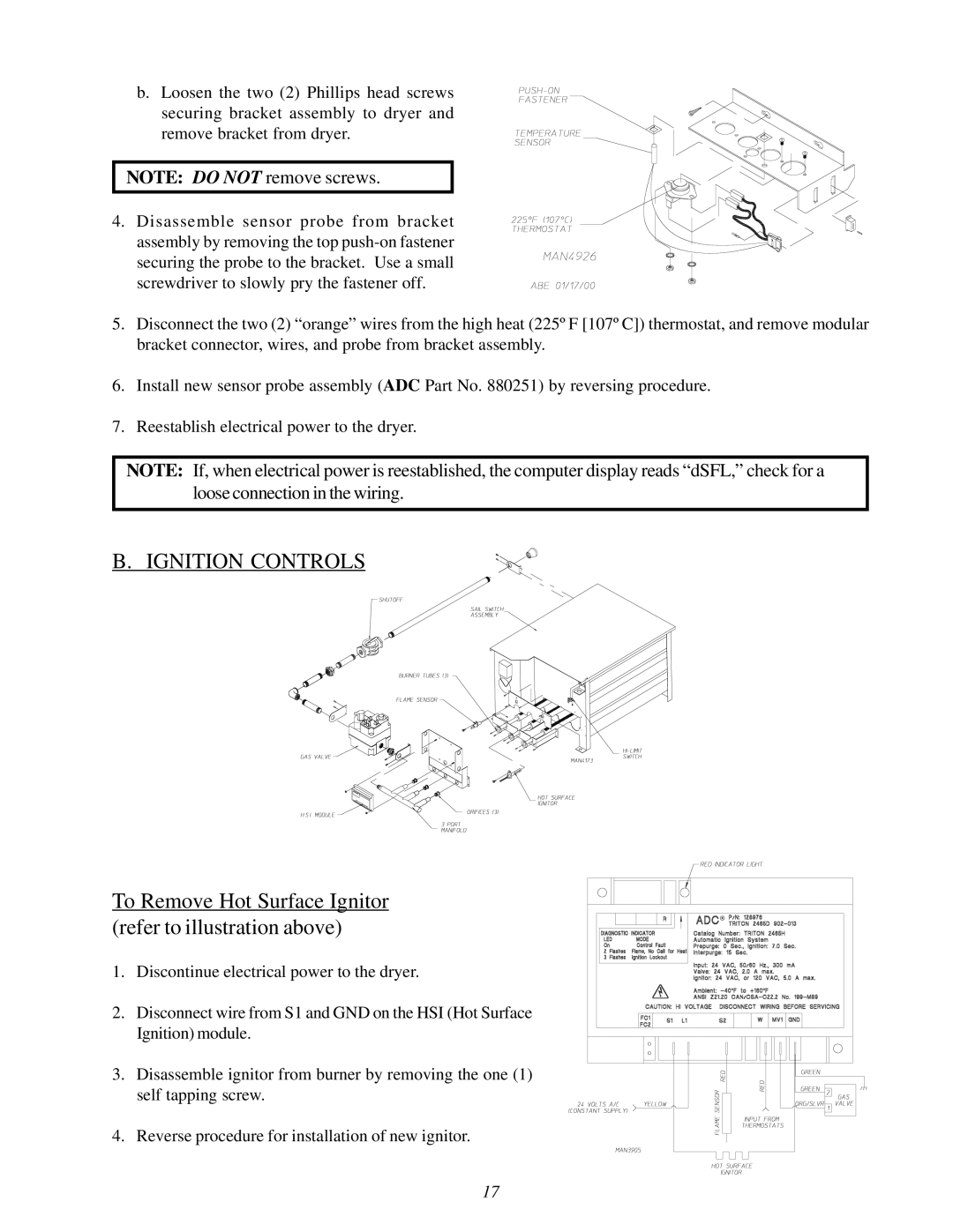
B. IGNITION CONTROLS
To Remove Hot Surface Ignitor (refer to illustration above)
1. Discontinue electrical power to the dryer.
2. Disconnect wire from S1 and GND on the HSI (Hot Surface Ignition) module.
3.Disassemble ignitor from burner by removing the one (1) self tapping screw.
4.Reverse procedure for installation of new ignitor.
17