To Replace Computer
1. Disconnect electrical power to the dryer.
2. Disconnect main power harness from rear of computer by squeezing locking tab and pulling connector straight back.
3. Disconnect the “green” ground wire from the computer.
4.Disconnect keyboard (touchpad) ribbon from computer.
5.Remove the two (2) hex nuts securing the computer to the sheet metal control panel. Remove the board by pulling the other two (2) corners off the clinch studs.
6.Install new computer by reversing this procedure. (refer to illustration on page 15.)
7.When replacing the computer, the “A” and “B” factors must be reprogrammed. (refer to Phase 6 OPL User’s Manual [ADC Part No. 113022].)
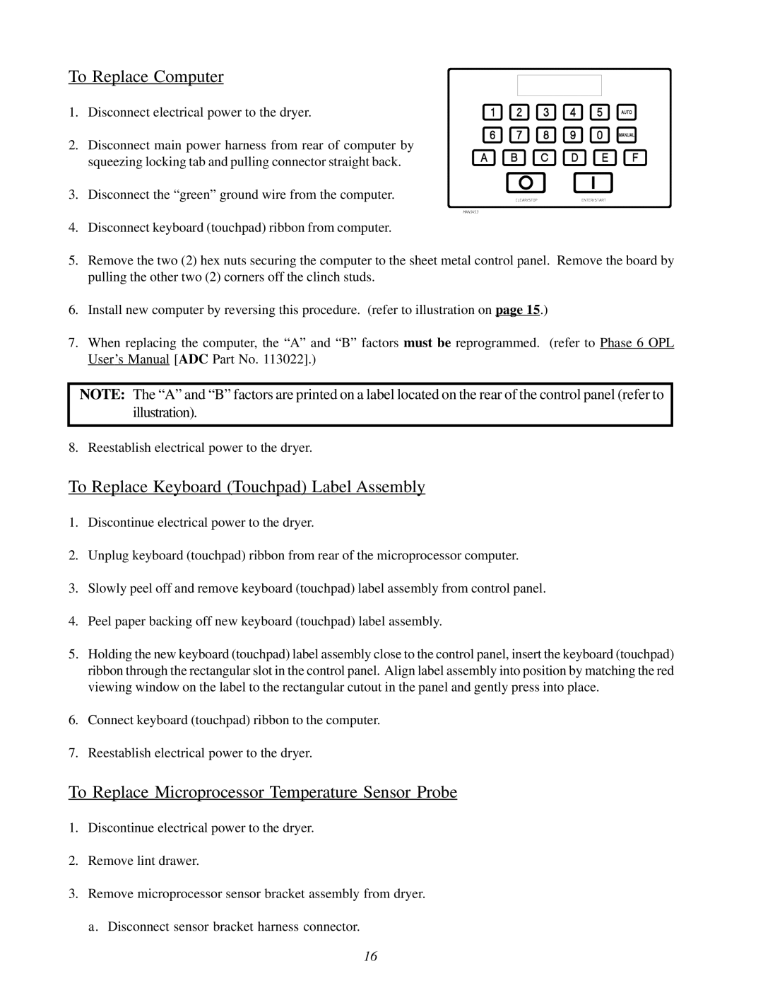
NOTE: The “A” and “B” factors are printed on a label located on the rear of the control panel (refer to illustration).
8. Reestablish electrical power to the dryer.
To Replace Keyboard (Touchpad) Label Assembly
1.Discontinue electrical power to the dryer.
2.Unplug keyboard (touchpad) ribbon from rear of the microprocessor computer.
3.Slowly peel off and remove keyboard (touchpad) label assembly from control panel.
4.Peel paper backing off new keyboard (touchpad) label assembly.
5.Holding the new keyboard (touchpad) label assembly close to the control panel, insert the keyboard (touchpad) ribbon through the rectangular slot in the control panel. Align label assembly into position by matching the red viewing window on the label to the rectangular cutout in the panel and gently press into place.
6.Connect keyboard (touchpad) ribbon to the computer.
7.Reestablish electrical power to the dryer.
To Replace Microprocessor Temperature Sensor Probe
1.Discontinue electrical power to the dryer.
2.Remove lint drawer.
3.Remove microprocessor sensor bracket assembly from dryer. a. Disconnect sensor bracket harness connector.
16