SECTION XI
PENDANT ASSEMBLY
A. PENDANT ASSEMBLY DESCRIPTION
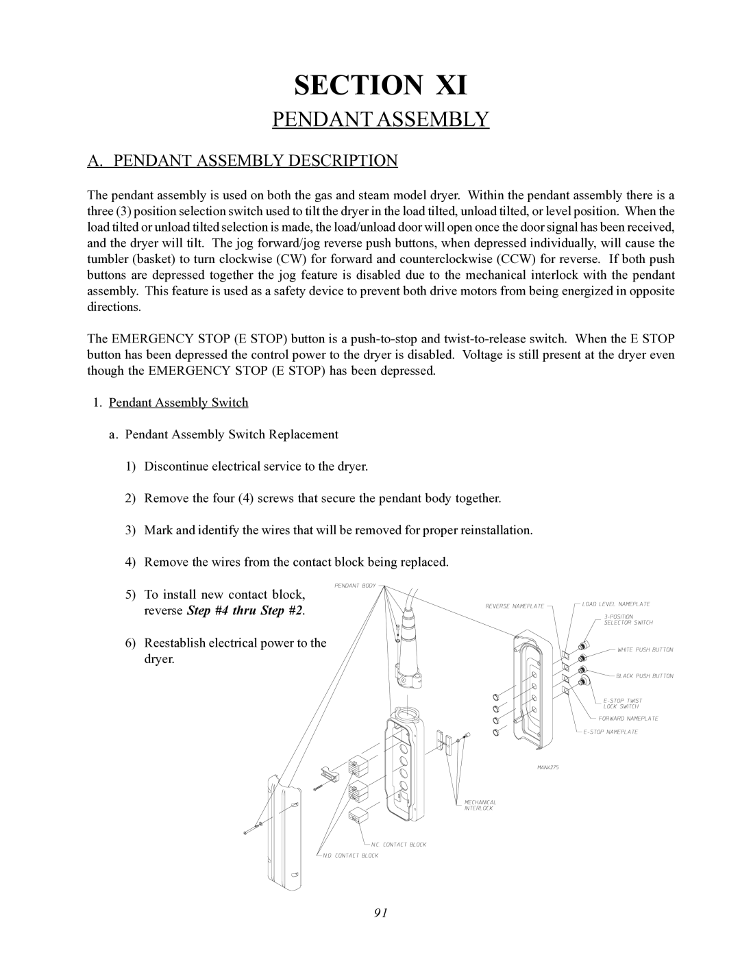
The pendant assembly is used on both the gas and steam model dryer. Within the pendant assembly there is a three (3) position selection switch used to tilt the dryer in the load tilted, unload tilted, or level position. When the load tilted or unload tilted selection is made, the load/unload door will open once the door signal has been received, and the dryer will tilt. The jog forward/jog reverse push buttons, when depressed individually, will cause the tumbler (basket) to turn clockwise (CW) for forward and counterclockwise (CCW) for reverse. If both push buttons are depressed together the jog feature is disabled due to the mechanical interlock with the pendant assembly. This feature is used as a safety device to prevent both drive motors from being energized in opposite directions.
The EMERGENCY STOP (E STOP) button is a
1.Pendant Assembly Switch
a. Pendant Assembly Switch Replacement
1)Discontinue electrical service to the dryer.
2)Remove the four (4) screws that secure the pendant body together.
3)Mark and identify the wires that will be removed for proper reinstallation.
4)Remove the wires from the contact block being replaced.
5)To install new contact block,
reverse Step #4 thru Step #2.
6) Reestablish electrical power to the dryer.
91
