CHAPTER 4
Understanding connectors
23
Table 2. addIT Receiver Pin Functions
1 | Bus Power (V+) |
|
|
2 | Bus Power (GND) |
|
|
3 | Bus Communications (B) |
|
|
4 | Bus Communications (A) |
|
|
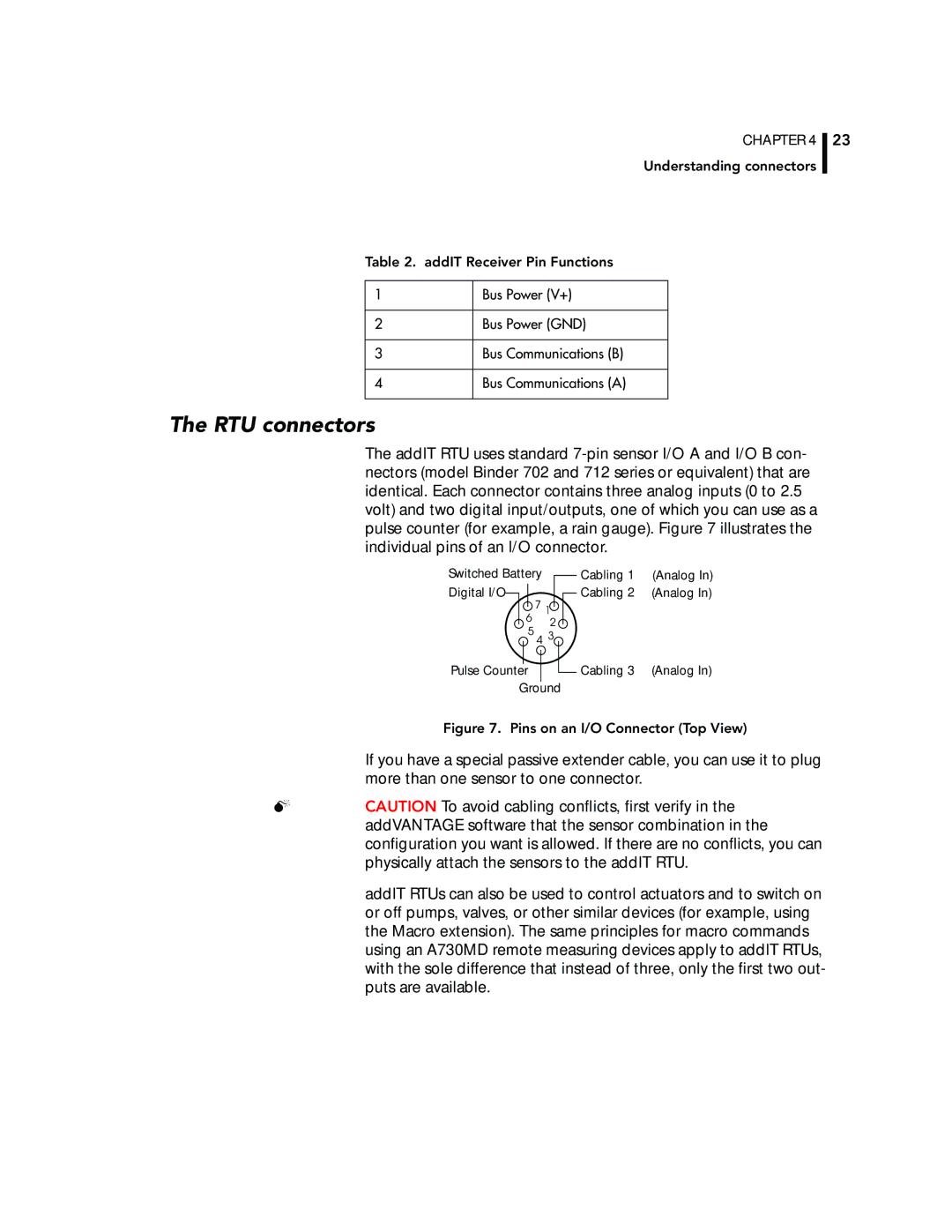
The RTU connectors
The addIT RTU uses standard
Switched Battery | Cabling 1 | (Analog In) |
Digital I/O | Cabling 2 | (Analog In) |
7 | 1 |
|
6 | 2 |
|
5 |
| |
3 |
| |
4 |
| |
Pulse Counter | Cabling 3 | (Analog In) |
Ground
Figure 7. Pins on an I/O Connector (Top View)
If you have a special passive extender cable, you can use it to plug more than one sensor to one connector.
CAUTION To avoid cabling conflicts, first verify in the addVANTAGE software that the sensor combination in the configuration you want is allowed. If there are no conflicts, you can physically attach the sensors to the addIT RTU.
addIT RTUs can also be used to control actuators and to switch on or off pumps, valves, or other similar devices (for example, using the Macro extension). The same principles for macro commands using an A730MD remote measuring devices apply to addIT RTUs, with the sole difference that instead of three, only the first two out- puts are available.