MX2800 STS-1
Trademark Information
REN FIC Usoc
Canadian Emissions Requirements
Canadian Equipment Limitations
Important Safety Instructions
Limited Product Warranty
Customer Service, Product Support Information, and Training
Repair and Return
61200659L1-1
Table of Contents
Configuration
Restore Defaults
Status
Statistics
Diagnostics
Index Index-1
Table of Contents Xviii
List of Figures
List of Figures
List of Tables
List of Tables Xxii
Introduction
Product Overview
Controller Card 11 Redundancy
STS-1 Pointers
STS-1 Overview
STS-1 Framing
Virtual Tributaries VT
Transport Overhead TOH
STS-1 Synchronous Payload Envelope SPE
Unit Timing
Snmp
Agent
Telnet
Network Manager
TL1
Breakout Panel P/N 1200291L1
Battery Backup P/N 4175043L2
Available Options
Adtran Shipments Include
UNPACK, INSPECT, Power UP
Receiving Inspection
Power Up
Power Loss Recovery
Backup system or equivalent
DC Connector Symbol Definitions
Alert user when connected to the 4175043L2 battery
Installation and Operation
Rackmount Installation
Be sure to install the flanges with the screws provided
Cable
Connecting the Breakout Panel
Front View Rear View
Rear Panel
Function
Modem Port
Noncritical and Critical Alarm Connectors
LAN Port
DSX-1/E1 Interfaces
Power Connection
Network Interfaces
Establishing Terminal Connection
Front Panel
Craft Port
Navigating Within the Menus
If you want to Press
ACO Buttons
Status LEDs
Power Supply A/B
LED Descriptions
LED Conditions for Active Cards
LED State Card Condition
LED Conditions for Standby Cards
T1/E1 Status LEDs
Active
T1/E1 LED Conditions
LED State T1/E1 Condition
Card
Configuration
Configuration Menu Tree
Line Length
STS-1 Configuration
Network Interface
Timing
XCV Threshold
VT Mode
Protection Configuration
Setting Unit switches controller cards if
Active Controller
Loopback Timeout
Max. Switch Threshold
Min. Switching Period
Miscellaneous
External Clock Configuration
VT Interface
T1 Coding
VT Interface #1-28
T1 State
Set Multiple
Set Cross-Connect Mapping
Set Multiple Menu
Restore VT Mapping Defaults
Protection Threshold
XCV Threshold
XCV Threshold Menu
System Management Configuration Menu
System Management
Management Options
Maximum Redial Attempts
Initializing String
Dial String
Pause Between Calls
Idle Timeout
Connection Timeout
Dialout On Trap
Hangup
Modem Mode
Modem Baud Rate
Last Modem Response
Alarm Relays
Alarm Relay Configuration
STS-1 Alarms Description
AIS-L
Alarm Description
SLM-P
VT/Port Alarms Description
VT-LOP
VT-RFI
System Alarms Description
Power Supply Alarms
Trap Generation
Snmp Management Options
Trap IP Addresses
Controller card has lost the network receive
Trap If enabled, the unit issues a trap when
LOS
RFI-L
VT/Port Traps If enabled, the unit issues a trap when
System Traps If enabled, the unit issues a trap when
LOS/AIS
Power Supply Alarm Traps
LOS/AIS
Write Community Name
MIB II Standard Alarm Traps
Read Community Name
Trap Community Name
System Security
Date & Time
Unit ID
Syslog Setup
Equipment Identification
STS-1 J1 Path Trace
Level Description Emergency
Error
Syslog Severity Levels
Alert
Utilities
Save on Logout
13. System Utilities Menu
If the self test results are Then
Update Via Xmodem
Load Default Settings
Update Flash Software
Saving to a Tftp Server
Config Transfer
Update via Tftp Server
Retrieving from a Tftp Server
System Reset
Save Configuration
Configuration
Status
Card a
Card A/Card B Alarms
STS-1 State
Condition Description
Controller card detects loss of H4 multiframe
Network Port Mapping
System State
Power Supply State
Alarm
Card A/Card B
Protection
Card Comm
Current Source
Timing Status
Clock Status
PRI Ext. Clock
SEC Ext. Clock
VT/Port State Alarm Description
VT/PORT State
Alarm Description cont’d
Acknowledge Alarms ACO
Statistics
Hour Alarm History
STS-1 Statistics
Following alarm counts are provided in this menu
Local STS-1 Current Alarm Count Screen
Local STS-1 24-Hour Alarm History Screen
Performance Parameters
Local STS-1 Performance Parameters Current 15 Minutes
Line Coding Violations LCV
Severely Errored Framing Seconds Sefs
Section Coding Violations SCV
Path Coding Violations PCV
Path Errored Seconds PES
Section Errored Seconds SES
Line Errored Seconds LES
Section Severely Errored Seconds Sses
Path Unavailable Seconds Puas
Local VT Statistics
Line Unavailable Seconds Luas
Clear All Local STS-1 Statistics
Alarm History
AIS
Local VT-LOP Alarm Count Screen Current 15 Minutes
SES
11. Local VT-CV Performance Parameters Current 15 Minutes
Bipolar Violation Counts
AIS Loop Alarms
Local Port Statistics
AIS Carrier Alarms
FAR END STS-1 Statistics
15. Far End STS-1 Performance Parameters Current 15 Minutes
Number of coding violations encountered at the Section layer
Section Errored Seconds SES
Clear All Far End STS-1 Statistics
Diagnostics
VT/PORT Loopbacks
Tributary
Analog Network
Tributary Loopback Test
Digital Line/Net
Codec Line/Net
CSU Loopback
CSU Loopback w/BERT
Diagnostics Menu with Bert Selected
VT Bert
Line Bert
VT Bert Test
STS-1 Loopbacks
Line Network
Analog Loopback
11. Line Network Test
Digital Loopback
13. Digital Loopback
Metallic Diagnostics
14. Metallic Diagnostics Loopback Test
Diagnostics
Circuit and Network Redundancy
NON-REDUNDANT Mode
Non-Redundant Mode
Circuit Failure Recovery Mode
Circuit Failure Recovery Mode
Circuit and Network Failure Recovery Mode
Circuit and Network Failure Recovery Mode
Circuit and Network Redundancy
Power Loss Recovery
NON-REDUNDANT Power Mode
Non-Redundant Power Mode
Power Supply Recovery Mode
Power Supply Failure Recovery Mode
Power Supply and Source Recovery Mode
Power Supply and Source Failure Recovery Mode
Battery Backup Mode
Battery Backup System
Power Loss Recovery
Introduction
Overview
Acknowledgment Messages
TL1 Messages
TL1 Responses
Output Response Messages
Progress
All Right
Autonomous Messages
TL1 Commands
ALW-MSG-EQPTrrALL
TL1 Commands
ACT-USERusernamepassword
DLT-USER-SECUuser
TL1 Commands ED-USER-SECUusername,password,,privileges
ENT-USER-SECUusernamepassword,,privileges
INH-MSG-EQPTrrALL
RTRV-HDR
RTRV-ALM-EQPTrrALL
Identifies the component to which the desired alarm
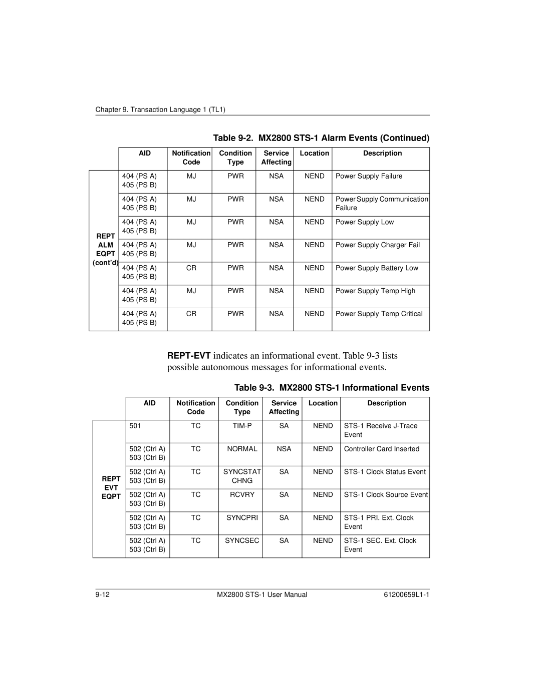
MX2800 STS-1 Alarm Events
TL1 Autonomous Messages
Eqpt
MX2800 STS-1 Informational Events
TL1 Error Codes
TL1 Error Codes
Transaction Language 1 TL1
Appendix a Pinouts
Table A-3. Modem Port Pin Assignments Description
Table A-2. LAN Port Pin Assignments
Pin
Table A-4. Amp Pin Assignments
Pin Function
Appendix A. Pinouts
DSX-1 Interfaces
Specifications and Features
DSX-3 Network Interface
Clocking
VT/Port Interfaces
Diagnostics STS-1 Network
Alarms
Management VT-100 Terminal Interface
Physical
Power
Environment
Appendix B. Specifications Summary
Appendix C Acronyms/Abbreviations
CRC
Febe
PES
UAS
Appendix C. Acronyms/Abbreviations
Appendix D Glossary
Bert
Ccitt
CPE
DCE
DSU
FDL
LOS
NRZ
SES
TDM
Yellow alarm
Index
Ethernet Failure
LOS
OOF
61200659L1-1 Index-5
Index-6