Main card. The Main card is installed in an
•Fiber Loss signal (either fiber)
•Laser degrade signal
•Module power supply failure
•Manual switch via the APS switch or a VT100 command
After the faulty circuit has been restored or following
a
NOTE
A manual switch can be performed only from the Working card.
Fiber (QFO-C) Menu Screen
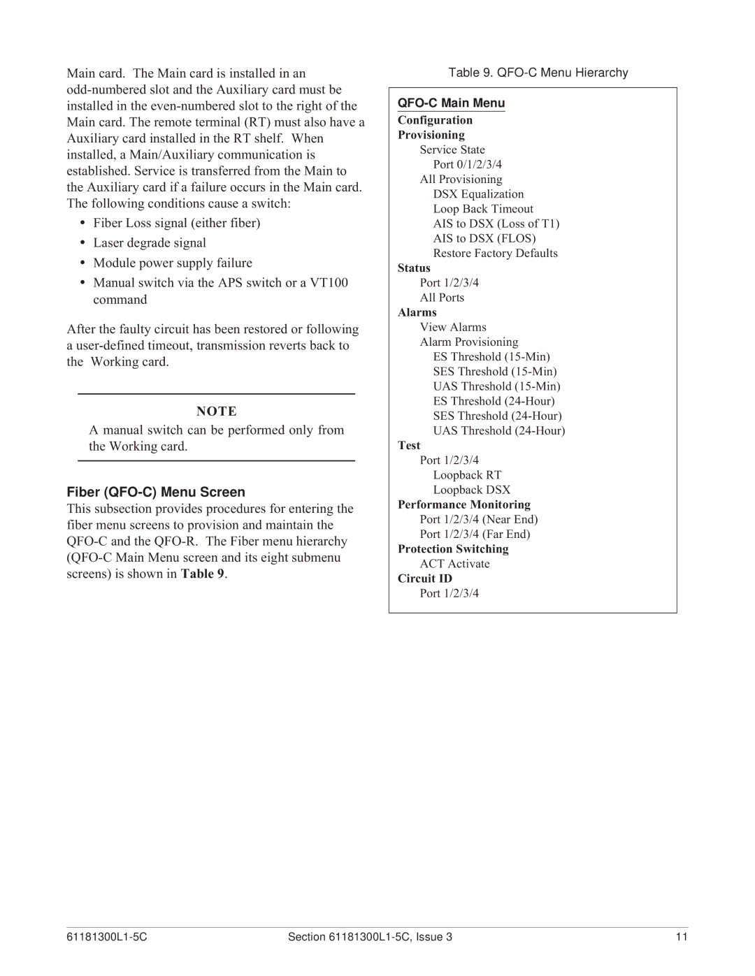
This subsection provides procedures for entering the fiber menu screens to provision and maintain the
Table 9.
QFO-C Main Menu
Configuration
Provisioning
Service State
Port 0/1/2/3/4
All Provisioning
DSX Equalization
Loop Back Timeout
AIS to DSX (Loss of T1)
AIS to DSX (FLOS)
Restore Factory Defaults
Status
Port 1/2/3/4
All Ports
Alarms
View Alarms
Alarm Provisioning
ES Threshold
SES Threshold
UAS Threshold
ES Threshold
SES Threshold
UAS Threshold
Test
Port 1/2/3/4
Loopback RT
Loopback DSX
Performance Monitoring
Port 1/2/3/4 (Near End)
Port 1/2/3/4 (Far End)
Protection Switching
ACT Activate
Circuit ID
Port 1/2/3/4
Section | 11 |