See Table 3 and Table 4 for Total Access 3000
For further details about
WARNING
Risk of electric shock. Voltages up to 140 Vdc (with reference to ground) may be present on telecommunications circuits.
1.Never install telephone wiring during a lightning storm.
2.Never install telephone jacks in wet locations unless the jack is specifically designed for wet locations.
3.Never touch uninsulated telephone wires or terminals unless the telephone line has been disconnected at the network interface.
4.Use caution when installing or modifying telephone lines.
5.This equipment is intended to be used behind devices that provide primary lightning protection.
6.Never look into the end of the fiber cable.
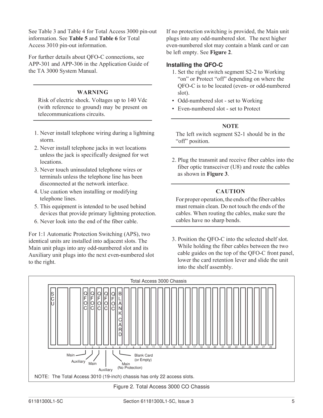
For 1:1 Automatic Protection Switching (APS), two identical units are installed into adjacent slots. The Main unit plugs into any
If no protection switching is provided, the Main unit plugs into any
Installing the QFO-C
1.Set the right switch segment
¥
¥
NOTE
The left switch segment
2.Plug the transmit and receive fiber cables into the fiber optic transceiver (U8) and route the cables as shown in Figure 3.
CAUTION
For proper operation, the ends of the fiber cables must remain clean. Do not touch the ends of the cables. When routing the cables, make sure the cables have no sharp bends.
3.Position the
Total Access 3000 Chassis
|
|
|
|
|
|
|
|
|
|
|
|
|
|
|
|
|
|
|
|
|
|
|
|
|
|
|
|
|
|
|
|
|
|
|
|
|
|
|
|
|
|
|
|
|
|
|
|
|
|
|
|
|
|
|
|
|
|
|
|
|
|
|
| S |
|
|
|
|
| Q |
| Q |
| Q |
| Q |
| Q |
| B |
|
|
|
|
|
|
|
|
|
|
|
|
|
|
|
|
|
|
|
|
|
|
|
|
|
|
|
|
|
|
|
|
|
|
|
|
|
|
|
|
|
|
|
|
|
| C |
|
|
|
|
| F |
| F |
| F |
| F |
| F |
| L |
|
|
|
|
|
|
|
|
|
|
|
|
|
|
|
|
|
|
|
|
|
|
|
|
|
|
|
|
|
|
|
|
|
|
|
|
|
|
|
|
|
|
|
|
|
| U |
|
|
|
|
| O |
| O |
| O |
| O |
| O |
| A |
|
|
|
|
|
|
|
|
|
|
|
|
|
|
|
|
|
|
|
|
|
|
|
|
|
|
|
|
|
|
|
|
|
|
|
|
|
|
|
|
|
|
|
|
|
|
|
|
|
|
|
| C |
| C |
| C |
| C |
| C |
| N |
|
|
|
|
|
|
|
|
|
|
|
|
|
|
|
|
|
|
|
|
|
|
|
|
|
|
|
|
|
|
|
|
|
|
|
|
|
|
|
|
|
|
|
|
|
|
|
|
|
|
|
|
|
|
|
|
|
|
|
|
|
| K |
|
|
|
|
|
|
|
|
|
|
|
|
|
|
|
|
|
|
|
|
|
|
|
|
|
|
|
|
|
|
|
|
|
|
|
|
|
|
|
|
|
|
|
|
|
|
|
|
|
|
|
|
|
|
|
|
|
|
|
|
|
| C |
|
|
|
|
|
|
|
|
|
|
|
|
|
|
|
|
|
|
|
|
|
|
|
|
|
|
|
|
|
|
|
|
|
|
|
|
|
|
|
|
|
|
|
|
|
|
|
|
|
|
|
|
|
|
|
|
|
|
|
|
|
| A |
|
|
|
|
|
|
|
|
|
|
|
|
|
|
|
|
|
|
|
|
|
|
|
|
|
|
|
|
|
|
|
|
|
|
|
|
|
|
|
|
|
|
|
|
|
|
|
|
|
|
|
|
|
|
|
|
|
|
|
|
|
| R |
|
|
|
|
|
|
|
|
|
|
|
|
|
|
|
|
|
|
|
|
|
|
|
|
|
|
|
|
|
|
|
|
|
|
|
|
|
|
|
|
|
|
|
|
|
|
|
|
|
|
|
|
|
|
|
|
|
|
|
|
|
| D |
|
|
|
|
|
|
|
|
|
|
|
|
|
|
|
|
|
|
|
|
|
|
|
|
|
|
|
|
|
|
|
|
|
|
|
|
|
|
|
|
|
|
|
|
|
|
|
|
|
|
|
|
|
|
|
|
|
|
|
|
|
|
|
|
|
|
|
|
|
|
|
|
|
|
|
|
|
|
|
|
|
|
|
|
|
|
|
|
|
|
|
|
|
|
|
|
|
|
|
|
|
|
|
|
|
|
|
|
|
| 1 | 2 | 3 | 4 | 5 |
| 6 | 7 | 8 | 9 | 10 | 11 | 12 | 13 | 14 | 15 | 16 | 17 | 18 | 19 | 20 | 21 | 22 | 23 | 24 | 25 | 26 | 27 | 28 |
| |||||||||||||||||||||||||||||||
Main
Auxiliary
|
| Blank Card |
Main |
| (or Empty) |
| Main | |
| Auxiliary | (No Protection) |
|
|
NOTE: The Total Access 3010
Figure 2. Total Access 3000 CO Chassis
Section | 5 |