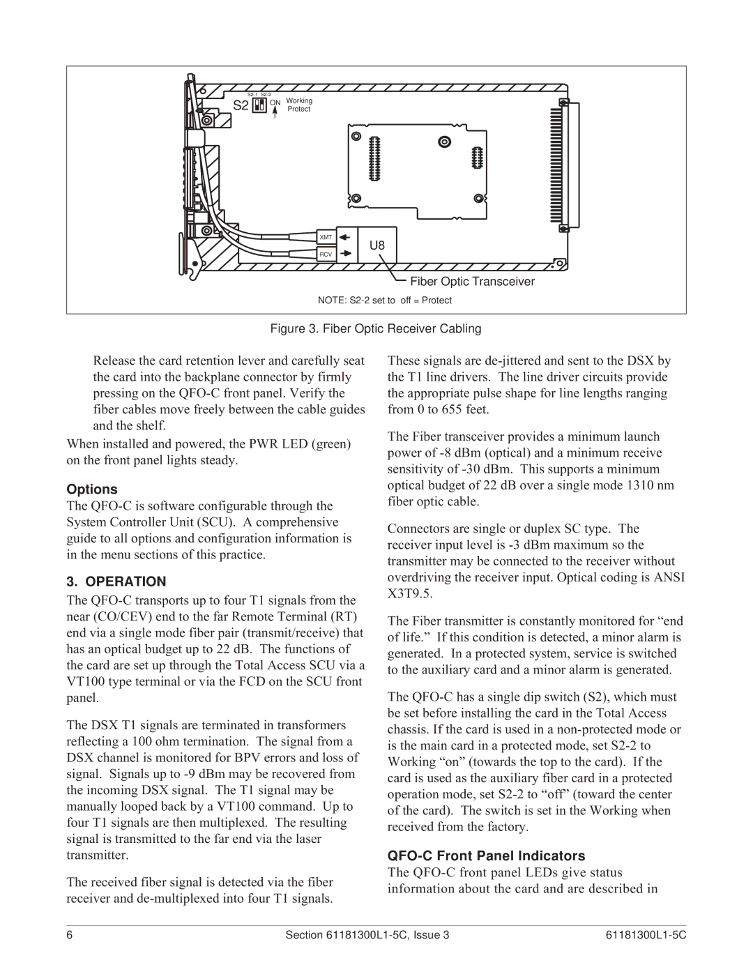
Release the card retention lever and carefully seat the card into the backplane connector by firmly pressing on the QFO-C front panel. Verify the fiber cables move freely between the cable guides and the shelf.
When installed and powered, the PWR LED (green) on the front panel lights steady.
Options
The QFO-C is software configurable through the System Controller Unit (SCU). A comprehensive guide to all options and configuration information is in the menu sections of this practice.
3. OPERATION
The QFO-C transports up to four T1 signals from the near (CO/CEV) end to the far Remote Terminal (RT) end via a single mode fiber pair (transmit/receive) that has an optical budget up to 22 dB. The functions of the card are set up through the Total Access SCU via a VT100 type terminal or via the FCD on the SCU front panel.
The DSX T1 signals are terminated in transformers reflecting a 100 ohm termination. The signal from a DSX channel is monitored for BPV errors and loss of signal. Signals up to -9 dBm may be recovered from the incoming DSX signal. The T1 signal may be manually looped back by a VT100 command. Up to four T1 signals are then multiplexed. The resulting signal is transmitted to the far end via the laser transmitter.
The received fiber signal is detected via the fiber receiver and de-multiplexed into four T1 signals.
These signals are de-jittered and sent to the DSX by the T1 line drivers. The line driver circuits provide the appropriate pulse shape for line lengths ranging from 0 to 655 feet.
The Fiber transceiver provides a minimum launch power of -8 dBm (optical) and a minimum receive sensitivity of -30 dBm. This supports a minimum optical budget of 22 dB over a single mode 1310 nm fiber optic cable.
Connectors are single or duplex SC type. The receiver input level is -3 dBm maximum so the transmitter may be connected to the receiver without overdriving the receiver input. Optical coding is ANSI X3T9.5.
The Fiber transmitter is constantly monitored for Òend of life.Ó If this condition is detected, a minor alarm is generated. In a protected system, service is switched to the auxiliary card and a minor alarm is generated.
The QFO-C has a single dip switch (S2), which must be set before installing the card in the Total Access chassis. If the card is used in a non-protected mode or is the main card in a protected mode, set S2-2 to Working ÒonÓ (towards the top to the card). If the card is used as the auxiliary fiber card in a protected operation mode, set S2-2 to ÒoffÓ (toward the center of the card). The switch is set in the Working when received from the factory.
QFO-C Front Panel Indicators
The QFO-C front panel LEDs give status information about the card and are described in