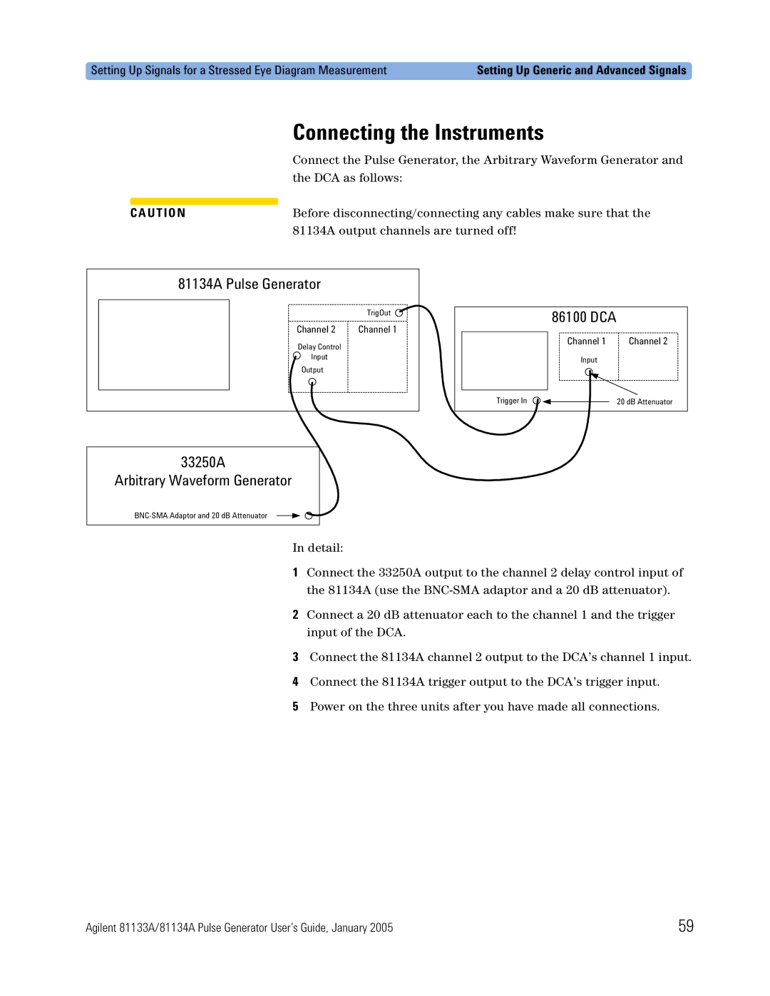
5988-7401EN specifications
Agilent Technologies, a leader in life sciences, diagnostics, and applied chemical markets, offers an array of sophisticated tools aimed at enhancing analytical and diagnostic capabilities. One such product is the Agilent 5988-7401EN, a high-performance mass spectrometer that exemplifies cutting-edge technology in the field of analytical chemistry.The Agilent 5988-7401EN is part of a series of mass spectrometers designed to deliver exceptional sensitivity and resolution for a variety of applications. This advanced instrument is particularly well-known for its versatility in mass spectrometry, enabling researchers to perform complex analyses with ease. Its flexibility makes it suitable for various industries, including pharmaceuticals, environmental testing, and food safety.
One of the standout features of the 5988-7401EN is its groundbreaking technology in ion detection. This mass spectrometer utilizes a unique technology that significantly enhances ion transmission and improves signal-to-noise ratios, resulting in more reliable and reproducible data. This capability is critical for trace analysis, where detecting low-abundance compounds is essential.
Moreover, the 5988-7401EN offers a wide mass range and fast scan speeds, making it suitable for both small molecule identification and larger biomolecules. This instrument can analyze complex mixtures with high accuracy, which is vital for researchers needing to understand intricate chemical compositions.
Additionally, the user-friendly interface of Agilent's mass spectrometer enhances productivity. With streamlined software that allows for easy operation and data analysis, researchers can efficiently set up experiments and interpret results, saving time and reducing the likelihood of human error.
Another important characteristic is its robustness and reliability. Built to withstand the demands of routine laboratory use, the 5988-7401EN ensures consistent performance over time, which is crucial for laboratories with high workloads.
In summary, the Agilent 5988-7401EN represents a significant advancement in mass spectrometry technology. With its impressive features, including exceptional sensitivity, a wide mass range, rapid scan speeds, and user-friendly software, it is an invaluable tool for researchers across various scientific disciplines. Whether it's for pharmaceutical development, environmental analysis, or food safety testing, the 5988-7401EN is designed to meet and exceed the analytical needs of modern laboratories.

