WLBARGS Manual
1.3 Hardware Introduction
Front Back
| 6 | |
1 |
| |
2 |
| |
3 | 7 | |
4 | ||
| ||
5 |
| |
| 8 | |
| 9 | |
| 10 |
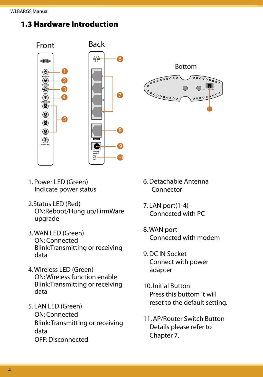
1.Power LED (Green) Indicate power status
2.Status LED (Red) ON:Reboot/Hung up/FirmWare upgrade
3.WAN LED (Green) ON: Connected Blink:Transmitting or receiving data
4.Wireless LED (Green)
ON: Wireless function enable Blink:Transmitting or receiving data
5.LAN LED (Green) ON: Connected
Blink: Transmitting or receiving data
OFF: Disconnected
Bottom
AP R outer
11
6.Detachable Antenna Connector
7.LAN
8.WAN port
Connected with modem
9.DC IN Socket Connect with power adapter
10.Initial Button
Press this buttom it will reset to the default setting.
11.AP/Router Switch Button Details please refer to Chapter 7.
4