System Example
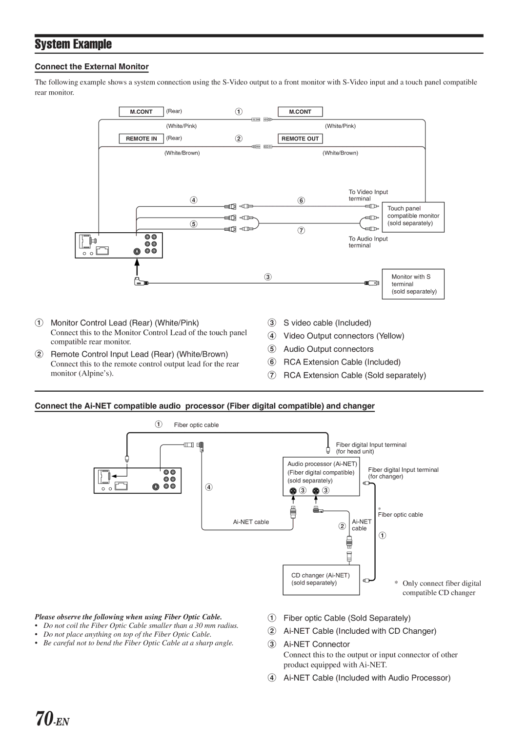
Connect the External Monitor
The following example shows a system connection using the
M.CONT
REMOTE IN
(Rear) | 1 |
(White/Pink) |
|
(Rear) | 2 |
(White/Brown) |
|
4
5
M.CONT
(White/Pink)
REMOTE OUT
(White/Brown)
To Video Input
6terminal
Touch panel compatible monitor (sold separately)
7
To Audio Input terminal
3
Monitor with S terminal
(sold separately)
1Monitor Control Lead (Rear) (White/Pink)
Connect this to the Monitor Control Lead of the touch panel compatible rear monitor.
2Remote Control Input Lead (Rear) (White/Brown)
Connect this to the remote control output lead for the rear monitor (Alpine’s).
3S video cable (Included)
4Video Output connectors (Yellow)
5Audio Output connectors
6RCA Extension Cable (Included)
7RCA Extension Cable (Sold separately)
Connect the
1Fiber optic cable
4
Fiber digital Input terminal (for head unit)
Audio processor
(Fiber digital compatible) | Fiber digital Input terminal | |
(for changer) | ||
(sold separately) | ||
|
![]() 3
3 ![]() 3
3
*
Fiber optic cable
2cable
1
Please observe the following when using Fiber Optic Cable.
•Do not coil the Fiber Optic Cable smaller than a 30 mm radius.
•Do not place anything on top of the Fiber Optic Cable.
•Be careful not to bend the Fiber Optic Cable at a sharp angle.
|
|
|
|
CD changer |
| ||
(sold separately) | * Only connect fiber digital | ||
|
|
| compatible CD changer |
1Fiber optic Cable (Sold Separately)
2
3
Connect this to the output or input connector of other product equipped with
4