| I NST ALLATIO | N | |
SI TE | INS TALLATIO N |
|
|
POS ITIONI NG REQUIREM ENTS |
|
| |
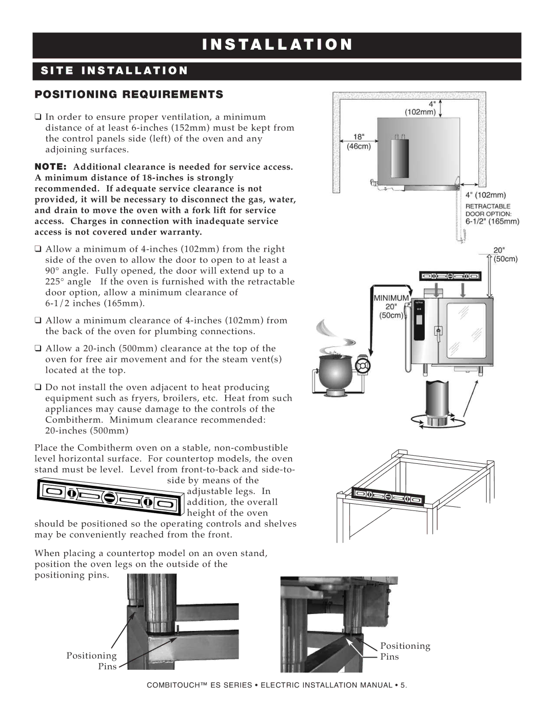
❑ In orde r to ensur e proper ventil atio n, a minim um |
| ||
distance of at lea st |
| ||
the cont rol panels side (left) of the oven and any |
| ||
adj oining surfaces. |
|
| |
NOTE : | Additional clearance is needed for servic e access. |
| |
A minimum distan ce of |
| ||
recomme nded. If adequate serv ice clearance is not |
| ||
provided, it will be necessary to disconnect | the gas, wate r, |
| |
and drain to mov e the oven with a fork lift for service |
| ||
acc ess. Charges in connection with inadequate service |
| ||
acc ess is not cover ed under warranty. |
|
| |
❑ Allow a minimum of |
| ||
side of the oven to allow the doo r to open to at least a |
| ||
90° angle . Fully opened , the door will extend up to a |
| ||
225° angle If the oven is furnished with | the retrac table |
| |
door option , allow a minimum clearance | of |
| |
|
| ||
❑ Allow a minimum clearan ce of |
| ||
the back of the oven for plumbi ng conne ctions. |
| ||
❑ Allow a 20- inch (500mm) clea rance at the top of the |
| ||
ove n for free air moveme nt and for the steam vent(s) |
| ||
loc ated at the top. |
|
| |
❑ Do not install the ove n adjac ent to heat prod ucing |
| ||
equ ipment such as fryers , broil ers, etc. Heat from such |
| ||
applian ces may cau se dama ge to the controls of the |
| ||
Combith erm . Min imum clearance recommend ed: |
| ||
|
| ||
Pla ce the Com bithe rm oven on a stabl e, |
| ||
lev el horizonta l surfa ce. For countertop models, the oven |
| ||
sta nd must be leve l. Level from front- |
| ||
| side by means of the |
| |
| adjustable legs. In |
| |
| addi tion, the overa ll |
| |
| heig ht of the oven |
| |
shoul d be positione d so the operati ng controls and she lves |
| ||
may be con ven ient ly reached from the front. |
| ||
When pla cing a count ert op mode l on an ove n stand, |
| ||
posi tion the ove n legs on the outside of the |
|
| |
posi tioning pins. |
|
| |
Posi tionin g
Pins
Posi tioni ng Pins
COMBITOUCH™ ES SERIES • ELECTRIC INSTALLATION MANUAL • 5.
