MATERIALS AND JOINING METHODS
![]() WARNING
WARNING
located in this section for specific details on termination construc- tion.
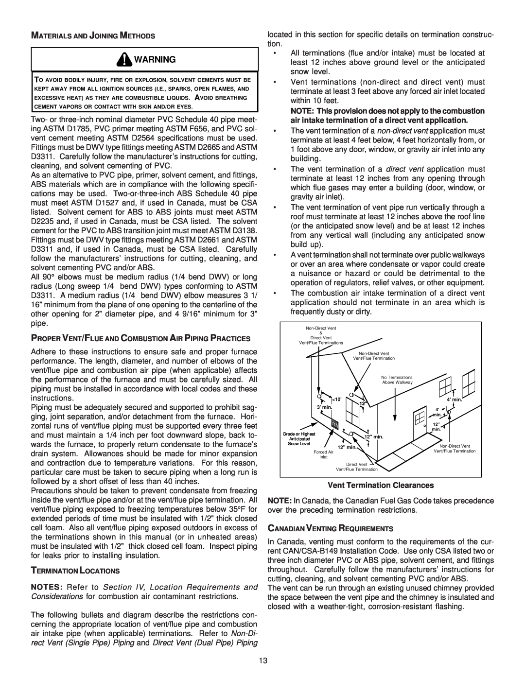
•All terminations (flue and/or intake) must be located at least 12 inches above ground level or the anticipated snow level.
TO AVOID BODILY INJURY, FIRE OR EXPLOSION, SOLVENT CEMENTS MUST BE KEPT AWAY FROM ALL IGNITION SOURCES (I.E., SPARKS, OPEN FLAMES, AND EXCESSIVE HEAT) AS THEY ARE COMBUSTIBLE LIQUIDS. AVOID BREATHING CEMENT VAPORS OR CONTACT WITH SKIN AND/OR EYES.
Two- or
As an alternative to PVC pipe, primer, solvent cement, and fittings, ABS materials which are in compliance with the following specifi- cations may be used.
All 90° elbows must be medium radius (1/4 bend DWV) or long radius (Long sweep 1/4 bend DWV) types conforming to ASTM D3311. A medium radius (1/4 bend DWV) elbow measures 3 1/ 16” minimum from the plane of one opening to the centerline of the other opening for 2” diameter pipe, and 4 9/16” minimum for 3” pipe.
PROPER VENT/FLUE AND COMBUSTION AIR PIPING PRACTICES
Adhere to these instructions to ensure safe and proper furnace performance. The length, diameter, and number of elbows of the vent/flue pipe and combustion air pipe (when applicable) affects the performance of the furnace and must be carefully sized. All piping must be installed in accordance with local codes and these instructions.
Piping must be adequately secured and supported to prohibit sag- ging, joint separation, and/or detachment from the furnace. Hori- zontal runs of vent/flue piping must be supported every three feet and must maintain a 1/4 inch per foot downward slope, back to- wards the furnace, to properly return condensate to the furnace’s drain system. Allowances should be made for minor expansion and contraction due to temperature variations. For this reason, particular care must be taken to secure piping when a long run is followed by a short offset of less than 40 inches.
•
•
•
•
•
•
Grade or Highest
Anticipated
Snow Level
12" min.
Forced Air
Inlet
Direct Vent
Vent/Flue Termination
4' min.
4' ![]()
![]()
![]() min.
min. ![]()
![]()
12"
min.
Vent/Flue Termination
Precautions should be taken to prevent condensate from freezing inside the vent/flue pipe and/or at the vent/flue pipe termination. All vent/flue piping exposed to freezing temperatures below 35°F for extended periods of time must be insulated with 1/2” thick closed cell foam. Also all vent/flue piping exposed outdoors in excess of the terminations shown in this manual (or in unheated areas) must be insulated with 1/2” thick closed cell foam. Inspect piping for leaks prior to installing insulation.
TERMINATION LOCATIONS
NOTES: Refer to Section IV, Location Requirements and Considerations for combustion air contaminant restrictions.
The following bullets and diagram describe the restrictions con- cerning the appropriate location of vent/flue pipe and combustion air intake pipe (when applicable) terminations. Refer to
Vent Termination Clearances
NOTE: In Canada, the Canadian Fuel Gas Code takes precedence over the preceding termination restrictions.
CANADIAN VENTING REQUIREMENTS
In Canada, venting must conform to the requirements of the cur- rent
The vent can be run through an existing unused chimney provided the space between the vent pipe and the chimney is insulated and closed with a
13