1 |
|
|
| 1 | 5 |
REMOVE |
| 2 |
| ||
4 SCREWS |
|
| REMOVE | 2" CLEARANCE | |
REMOVE |
| ||||
| 2 | 4 SCREWS | REQUIRED | ||
|
|
| |||
|
|
|
| ||
|
| REMOVE |
| VENT) | |
|
| AND CUT |
|
| |
|
| 3 | 1 |
|
|
|
| REMOVE |
|
| |
|
| REMOVE 3 SCREWS |
|
| |
|
| AND | 3 |
|
|
|
| RELOCATE |
|
| |
|
| ADDITIONAL |
|
| |
|
| PLUG FROM |
|
| |
|
| DRAIN KIT |
| 3. | |
|
|
|
|
| REMOVE |
|
|
|
|
| AND |
UPFLOW |
|
|
| RELOCATE | |
|
| COUNTERFLOW |
| ||
| 4 |
| 5 |
|
|
SECURE |
|
|
|
| |
TO CABINET |
|
|
| ||
UPFLOW/HORIZONTAL SHOWN
(COUNTERFLOW SIMILAR)
Alternate Combustion Air Intake Location
Although
VENT/FLUE PIPE LENGTHS AND DIAMETERS
Refer to the following table for applicable length, elbows, and pipe diameter for construction of the vent/flue pipe system of a
|
|
| UPFLOW |
|
|
|
|
| ||
|
|
|
| |||||||
Maximum Allowable Length of Vent/Flue Pipe (ft) (1)(2) |
| |||||||||
Unit Input | Pipe (4) |
|
| Number of Elbows (3) |
|
| ||||
| (Inch) | 1 | 2 | 3 |
| 4 | 5 | 6 | 7 | 8 |
45,000 | 2 | 71 | 68 | 65 |
| 62 | 59 | 56 | 53 | 50 |
70,000 | 2 | 49 | 46 | 43 |
| 40 | 37 | 34 | 31 | 28 |
3 | 71 | 68 | 65 |
| 62 | 59 | 56 | 53 | 50 | |
|
| |||||||||
90,000 | 3 | 71 | 68 | 65 |
| 62 | 59 | 56 | 53 | 50 |
115,000 | 3 | 49 | 46 | 43 |
| 40 | 37 | 34 | 31 | 28 |
|
|
|
|
|
|
| ||||
|
| COUNTERFLOW |
|
|
|
| ||||
|
|
|
| |||||||
Maximum Allowable Length of Vent/Flue Pipe (ft) (1)(2) |
| |||||||||
Unit Input | Pipe (4) |
|
| Number of Elbows (3) |
|
| ||||
| (Inch) | 1 | 2 | 3 |
| 4 | 5 | 6 | 7 | 8 |
70,000 | 2 | 61 | 58 | 55 |
| 52 | 49 | 46 | 43 | 40 |
3 | 71 | 68 | 65 |
| 62 | 59 | 56 | 53 | 50 | |
|
| |||||||||
90,000 | 2 | 61 | 58 | 55 |
| 52 | 49 | 46 | 43 | 40 |
3 | 71 | 68 | 65 |
| 62 | 59 | 56 | 53 | 50 | |
|
| |||||||||
(1)One 90° elbow should be secured to the combustion air intake con- nection.
(2)Minimum vent length is five feet and one elbow/tee.
(3)Tee used in the vent/flue termination must be included when determin- ing the number of elbows in the piping system.
(4)3” diameter pipe can be used in place of 2” diameter pipe.
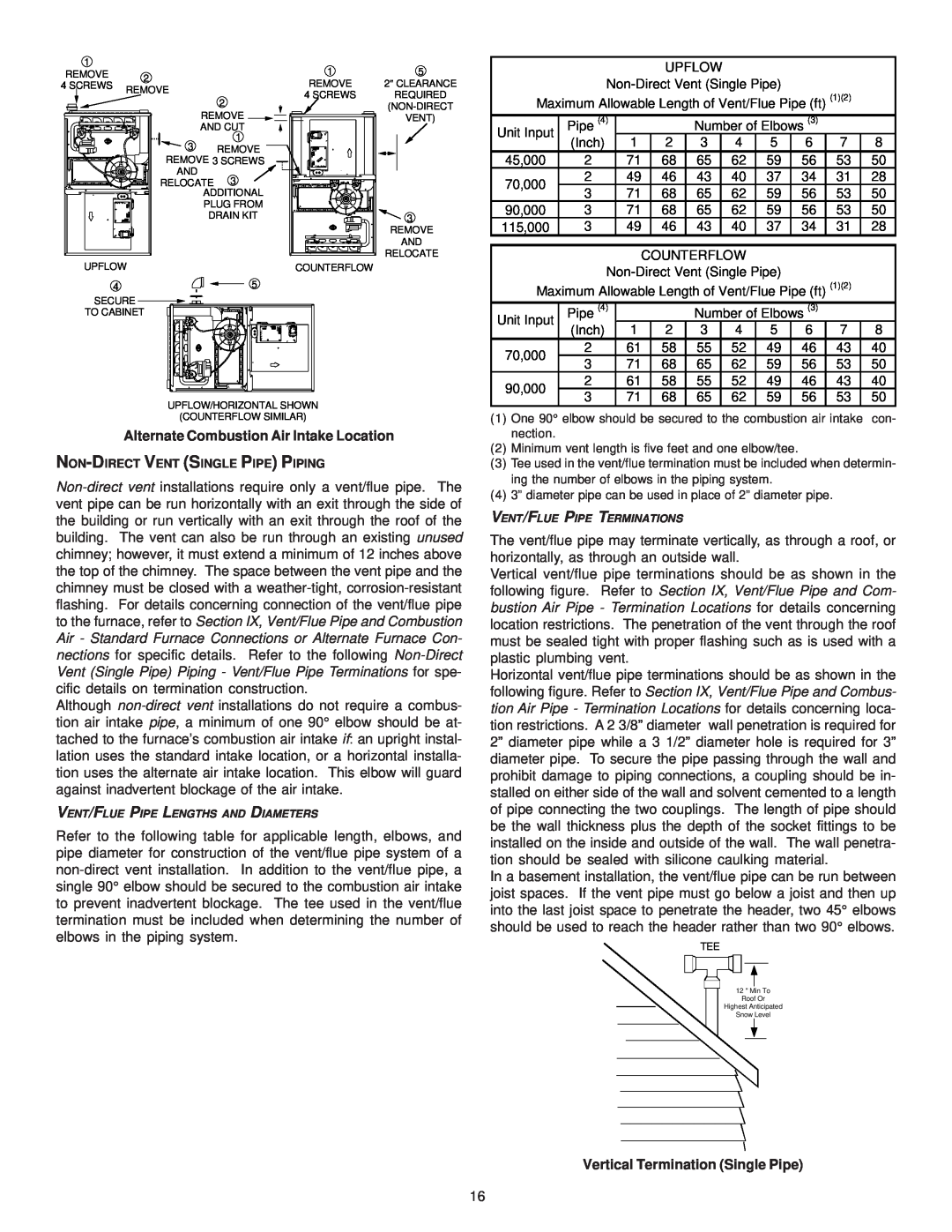
VENT/FLUE PIPE TERMINATIONS
The vent/flue pipe may terminate vertically, as through a roof, or horizontally, as through an outside wall.
Vertical vent/flue pipe terminations should be as shown in the following figure. Refer to Section IX, Vent/Flue Pipe and Com- bustion Air Pipe - Termination Locations for details concerning location restrictions. The penetration of the vent through the roof must be sealed tight with proper flashing such as is used with a plastic plumbing vent.
Horizontal vent/flue pipe terminations should be as shown in the following figure. Refer to Section IX, Vent/Flue Pipe and Combus- tion Air Pipe - Termination Locations for details concerning loca- tion restrictions. A 2 3/8” diameter wall penetration is required for 2” diameter pipe while a 3 1/2” diameter hole is required for 3” diameter pipe. To secure the pipe passing through the wall and prohibit damage to piping connections, a coupling should be in- stalled on either side of the wall and solvent cemented to a length of pipe connecting the two couplings. The length of pipe should be the wall thickness plus the depth of the socket fittings to be installed on the inside and outside of the wall. The wall penetra- tion should be sealed with silicone caulking material.
In a basement installation, the vent/flue pipe can be run between joist spaces. If the vent pipe must go below a joist and then up into the last joist space to penetrate the header, two 45° elbows should be used to reach the header rather than two 90° elbows.
TEE
12 " Min To
Roof Or
Highest Anticipated
Snow Level
Vertical Termination (Single Pipe)
16