| CENTRAL |
| RETURN |
| GRILLE |
FILTER | SIDE RETURN |
EXTERNAL FILTER | |
RACK KIT | |
| (EITHER SIDE) |
![]()
![]() FILTER
FILTER
FILTER
ACCESS
DOOR
AIR FLOW | RETURN |
| DUCT |
FILTER
SUPPORT BRACKET (PROVIDED)
FIL ![]() T ER
T ER
ILTER F
FILTER
CENTRAL RETURN GRILLE
position.
6.Wait five minutes then smell for gas. Be sure check near the floor as some types of gas are heavier than air.
7.If you smell gas after five minutes, immediately follow the instructions on page 4 of this manual. If you do not smell gas after five minutes, move the furnace gas valve manual control to the ON position.
8.Replace the burner compartment door.
9.Open the manual gas shutoff valve external to the furnace.
10.Turn on the electrical power to the furnace.
11.Adjust the thermostat to a setting above room temperature.
12.After the burners are lit, set the thermostat to desired temperature.
FURNACE SHUTDOWN
| AIR FLOW |
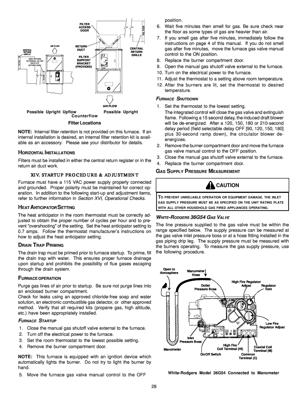
Possible Upright Upflow | Possible Upright |
Counterflow |
|
Filter Locations
NOTE: Internal filter retention is not provided on this furnace. If an internal installation is desired, an internal filter retention kit is avail- able as an accessory. Please see your distributor for details.
HORIZONTAL INSTALLATIONS
Filters must be installed in either the central return register or in the return air duct work.
XIV. STARTUP PROCEDURE & ADJUSTMENT
Furnace must have a 115 VAC power supply properly connected and grounded. Proper polarity must be maintained for correct op- eration. In addition to the following
HEAT ANTICIPATOR SETTING
The heat anticipator in the room thermostat must be correctly ad- justed to obtain the proper number of cycles per hour and to pre- vent “overshooting” of the setting. Set the heat anticipator setting to
0.7amps. Follow the thermostat manufacturer’s instructions on how to adjust the heat anticipator setting.
DRAIN TRAP PRIMING
The drain trap must be primed prior to furnace startup. To prime, fill the drain trap with water. This ensures proper furnace drainage upon startup and prohibits the possibility of flue gases escaping through the drain system.
FURNACE OPERATION
Purge gas lines of air prior to startup. Be sure not purge lines into an enclosed burner compartment.
Check for leaks using an approved
FURNACE STARTUP
1.Close the manual gas shutoff valve external to the furnace.
2.Turn off the electrical power to the furnace.
3.Set the room thermostat to the lowest possible setting.
4.Remove the burner compartment door.
NOTE: This furnace is equipped with an ignition device which automatically lights the burner. Do not try to light the burner by hand.
5. Move the furnace gas valve manual control to the OFF
1.Set the thermostat to the lowest setting.
The integrated control will close the gas valve and extinguish flame. Following a 15 second delay, the induced draft blower will be
2.Remove the burner compartment door and move the furnace gas valve manual control to the OFF position.
3.Close the manual gas shutoff valve external to the furnace.
4.Replace the burner compartment door.
GAS SUPPLY PRESSURE MEASUREMENT
![]() CAUTION
CAUTION
TO PREVENT UNRELIABLE OPERATION OR EQUIPMENT DAMAGE, THE INLET GAS SUPPLY PRESSURE MUST BE AS SPECIFIED ON THE UNIT RATING PLATE WITH ALL OTHER HOUSEHOLD GAS FIRED APPLIANCES OPERATING.
The line pressure supplied to the gas valve must be within the range specified below. The supply pressure can be measured at the gas valve inlet pressure boss or at a hose fitting installed in the gas piping drip leg. The supply pressure must be measured with the burners operating. To measure the gas supply pressure, use the following procedure.
Open to | Manometer |
|
| |
Atmosphere |
|
| ||
Hose |
|
| ||
|
|
| ||
| Outlet | High Fire Regulator | ||
| Adjust | Regulator | ||
| Pressure Boss |
| Vent | |
|
| A |
| |
|
|
| Low Fire | |
|
|
| Regulator Adjust | |
| Inlet |
|
| |
Pressure Boss | High Fire |
| ||
|
| Coaxial Coil | ||
Manometer | Coil Terminal (HI) | |||
Terminal (M) | ||||
|
|
| ||
| On/Off Switch | Common | ||
|
| Terminal (C) | ||
28