Preface
Greensmaster 3100/3050
This page is intentionally blank
Table Of Contents
This page is intentionally blank
Safety Instructions
Safety Instructions
Chapter
Before Operating
While Operating
Safety Instructions Greensmaster
Safety Instructions
Safety Instructions Greensmaster
2 1 Rev.. DB Product Records
Product Records
Decimal and Millimeter Equivalents
Equivalents and Conversions
To Metric Conversions
Equivalents and Conversions Greensmaster
Torque Specifications
Torque Specifications
Capscrew Markings and Torque Values U.S. Customary
Capscrew Markings and Torque Values Metric
This page is intentionally blank
Specifications
Specification
3 1 Rev. D Specifications
Throttle Control Adjustment Fig
Adjustments
Choke Control Adjustment Fig
Adjustments Greensmaster
Governor Lever Adjustment Fig
Governor Adjustment Before starting engine
Throttle Restrictor Adjustment Fig
Secondary Spring Adjustments Fig
Warnin G
Carburetor and Speed Control Adjustment
Engine Removal and Installation
Installing the Engine
Removing the Engine
Engine Removal and Installation Greensmaster
Hydraulic System
Table of Contents
Description
Specifications 4 2 Rev. D
General Information
Hydraulic Fitting Installation
Hydraulic Hoses
Ring Face Seal
SAE Straight Thread O-Ring Port Non-adjustable Fig
SAE Straight Thread O-Ring Port Adjustable
General Information Greensmaster
Traction, No Position
Hydraulic Flow Diagrams
Hydraulic Flow Diagrams Greensmaster
Traction, Reverse Position
Reel Drive, Mowing Operation
Hydraulic Flow Diagrams 4 8 Rev. E Greensmaster3100
4 9 Rev. E
Reel Drive, Lower Cutting Units
Reel Drive, Raising Cutting Units
Hydraulic Flow Diagrams 4 10 Rev. E
4 11 Rev. E
Power Steering, R.H. Turn Greensmaster
Hydraulic Schematics
Hydraulic Schematic Greensmaster 3100 2WD Serial
Rev. E
Hydraulic Schematics 4 12.2 Rev. E
Hydraulic Schematic Greensmaster 3100 3WD
12.3
Hydraulic Schematic
Hydraulic Schematics 4 12.4 Rev. E Greensmaster
Hydraulic Tester Fig
Special Tools
Detent Installation Tool Fig
Seal Protector Fig
Special Tools Greensmaster
Seal Installation Tool Fig
Assembly Studs Fig
Control Valve Spool Seal Installation Tools Fig
Troubleshooting Greensmaster
Troubleshooting
Slow Groundspeed in All Traction Selections
Troubleshooting
Slow or No Ground Speed in No and Reverse No Appears Normal
No Increase in Speed from No to No
One or More Cutting Units Slow or No Reel Drive Action
All Reels Slow or Will Not Turn
Mow Pedal Won’t Stay Engaged Reels Slow Down or Stop
Cutting Units Drop During Transport
Cutting Units Lift Too Slowly or Not At All
Center #1 Cutting Unit Operates in Raised Position
Lift Pedal Binding
Steering Loss, Steering Wander or Free Play
Testing
Testing
Traction Pump Flow Traction Relief Setting
Engine when the traction lever is engaged
Testing Greensmaster
Test Hook UP no
Test B Relief Valve Setting Procedure
Test Hook UP NO.2
4 30 Rev. E Testing
Test Hook UP NO.2
Testing 4 31 Rev. E Greensmaster
Engine when the mow pedal is engaged
Testing 4 32 Rev. E Greensmaster3100
Reel Drive Pump Efficiency
4 33 Rev. E Testing
Test a Reel Drive Motor Flow Procedure
Test Hook UP no
4 35 Rev. E Testing
Test Hook UP no Greensmaster
Steering Pump Flow and Relief Pressure
Lift and Mow Pedal Height Adjustment Fig
4 37 Rev. B Adjustments
Traction Pedal Adjustment Fig
Traction Return Linkage a
Reverse
Rear Camshaft Adjustment Fig
Reel Motor Shaft Seal Replacement Fig
Reel Motor Removal and Installation Fig
Repairs
Repairs
Repairs 4 40 Rev. B
Reel Motor 70-9800 Repair Fig
Repairs
Repairs 4 41.1 Rev. B Greensmaster
Reel Motor 94-3506 Repair a
Greensmaster 4-41.2 Rev. B Repairs
Disassembly
Reel Motor 105-9770 Repair b
Repairs 4 41.3 Rev. D Greensmaster
Greensmaster 4-41.4 Rev. D Repairs
Inspection
Repairs 4 41.5 Rev. D Greensmaster
Reassembly
This page is intentionally blank
Repairs Greensmaster
Pump Repair Greensmaster 3100 shown Fig Relief Valve Service
Repairs Greensmaster
Control Valve Removal and Installation Fig
Relief Valve Removal and Installation Fig
Greensmaster Repairs
Rear Bonnet Side Fig
Control Valve Spool Seal Replacement
Control Valve Internal Seal Replacement Fig
Control Valve No Spool Detent Replacement
Reassemble With the Following Procedures
Control Valve No Spool Detent Replacement Fig
No Center Lift Cylinder Fig
Lift Cylinder Removal and Installation
No and 3 Lift Cylinders Fig
Lift Cylinder Repair No Center Fig
Lift Cylinder Repair No and 3 Left and Right Fig
Wheel Motor Removal and Installation Fig
Wheel Motor Repair
Disassembly of Motor Fig
Before Assembling Motor
Assembly of Motor
Rotor, Stator and Vane Assembly
Reverse steps 1 3 to install the steering cylinder
Steering Cylinder Repair Greensmaster 3100 Fig
Repairs Greensmaster
Steering Control Unit Repair Greensmaster 3100 Fig
Meter Gerotor End Disassembly
Control End Disassembly
Push pin from spool and sleeve assembly
Repairs
Control End Reassembly
Repairs
Repairs Greensmaster
Repairs
Repairs Greensmaster
Repairs
Repairs Greensmaster
Electrical System
Wiring Schematics 5 2 Rev. D Greensmaster
Wiring Schematic Greensmaster 3100, S/N Below
Wiring Schematic Greensmaster 3100, S/N 80001
Wiring Schematics
5 2.1 Rev. D
Greensmaster 3100, S/N
Wiring Schematic
220999999
5 2.2 Rev. D
Wiring Schematic
Wiring Schematics 5 2.4 Rev. D Greensmaster 3100/3050
Wiring Schematic Greensmaster 3050, S/N Below
5 2.5 Rev. D Wiring Schematics
Wiring Schematic Greensmaster 3050, S/N 80001
Wiring Schematics 5 2.6 Rev. D
Wiring Schematic Greensmaster 3050, S/N 230000001 and Up
200999999
3100/3050
This page is intentionally blank
Before Start-Up Cold Oil
Normal Operation Warm Oil
Leak Alert
Volt Ohm Amp Meter Fig
Continuity Tester Fig
Skin-Over Grease Fig
Condition Cause Correction
Problem Cause Correction
Verify Interlock Operation
Ignition Key Switch Fig
Traction Neutral Switch Fig
Seat Switch Fig
Interlock Module Fig
Mow/Lift Switch Fig
Battery
Hourmeter
Turf Guardian TM Leak Detector System
Seat Switch Replacement and Adjustment Fig
General Safety Interlock Switch Service
Traction Neutral Switch Replacement and Adjustment Fig
Wiring Harness Service
Mow/Lift Switch Replacement and Adjustment Fig
Battery Specifications
Battery Service
6 1 Rev. B
Wheels, Steering and Brakes
Specifications Greensmaster
Brake Adjustment Fig
Brake Disassembly Reassembly
Brake Service Fig
Steering Arm Greensmaster
Steering Cable Greensmaster
6 5 Rev. B Repairs
Repairs 6 6 Rev. B Greensmaster
Bolt Adjust Cutting Units
Page
Page
Page
Page
Page
Page
Use Loctite 271 on spline nut Rev. C
Page
Page
Page
Page
Page
Page
Page
Page
Page
Page
Use Loctite 271 on spline nut Rev. C
Page
Single Point Adjust Cutting Units
Page
Page
Page
Page
Page
Page
Page
Page
Use Loctite 271 on spline nut threads Rev. C
Page
Page
Page
Page
Page
Page
Page
Page
Page
Page
Page
Page
Page
Use Loctite 271 on spline nut threads Rev. C
Page
Page
For Four Bolt Adjust and Single Point Adjust Cutting Units
Introduction
9 1 Rev. D Introduction
Page
Page
Page
Page
Page
Page
Page
Page
Page
Page
Use Loctite 271 on spline nut threads Rev. C
Page
Page
Page
Page
Page
Page
Page
Page
Page
Page
Page
Page
Page
Page
Use Loctite 271 on spline nut threads Rev. C
Page
Page
Page
Page
Page
Page
This page is intentionally blank
10 1 Rev. D Dual Point Adjust Cutting units
Dual Point Adjust Cutting Units
Weight
Dual Point Adjust Cutting Units 10 2 Rev. D
Maximum Reel Speed 2200 RPM
Backlapping Brush Assembly
Gauge Bar Assembly
10 3 Rev. D Dual Point Adjust Cutting units
Bedknife Screw Tool
Dual Point Adjust Cutting Units 10 4 Rev. D Greensmaster
Inner Grease Seal Installation Washer
Plastic Plug
Turf Evaluator Tool
After installation to the bedbar
Factor Possible Problem/Correction
10 5 Rev. D Dual Point Adjust Cutting units
Factors That Can Affect Quality of Cut
Dual Point Adjust Cutting Units 10 6 Rev. D Greensmaster
Set Up and Adjustments
Characteristics
10 7 Rev. D Dual Point Adjust Cutting units
Dual Point Adjust Cutting Units 10 8 Rev. D Greensmaster
Installation
Hydraulic Reel Motor
Removal
To Avoid Personal Injury or Death
10 9 Rev. D Dual Point Adjust Cutting units
Dual Point Adjust Cutting Units 10 10 Rev. D Greensmaster
Bedbar Assembly
Installation Fig
Bedbar Removal and Installation
10 11 Rev. D Dual Point Adjust Cutting units
Removal Fig
Dual Point Adjust Cutting Units 10 12 Rev. D Greensmaster
Bedbar Adjuster Service
Replacement
Bedknife Replacement and Grinding
10 13 Rev. D Dual Point Adjust Cutting units
Grinding
Dual Point Adjust Cutting Units 10 14 Rev. D Greensmaster
Reel Assembly
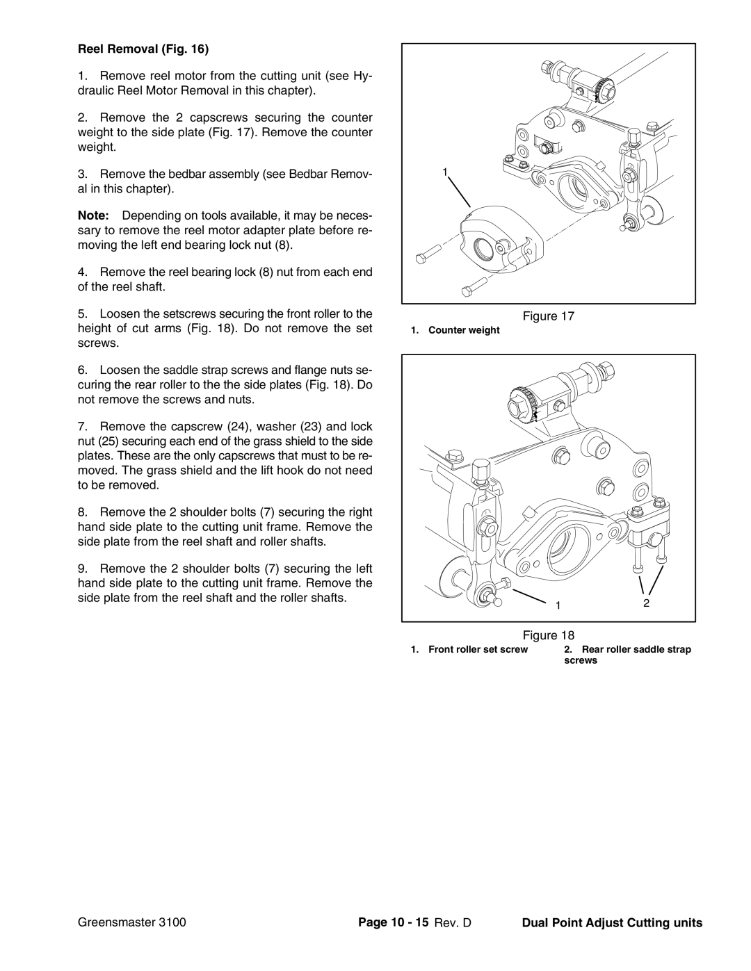
Reel Removal Fig
10 15 Rev. D Dual Point Adjust Cutting units
Left Side Plate Service Fig
Right Side Plate Service Fig
Dual Point Adjust Cutting Units 10 16 Rev. D Greensmaster
10 17 Rev. D Dual Point Adjust Cutting units
Reel Service Fig
Dual Point Adjust Cutting Units 10 18 Rev. D Greensmaster
Reel Installation Fig
Preparing a Reel for Grinding
10 19 Rev. D Dual Point Adjust Cutting units
Dual Point Adjust Cutting Units 10 20 Rev. D Greensmaster
Front Roller Removal and Installation
Seal Installation
Front and Rear Roller Service
10 21 Rev. D Dual Point Adjust Cutting units
Seal Removal
Bearing Installation
Dual Point Adjust Cutting Units 10 22 Rev. D Greensmaster
Bearing Removal
This page is intentionally blank
Commercial Products