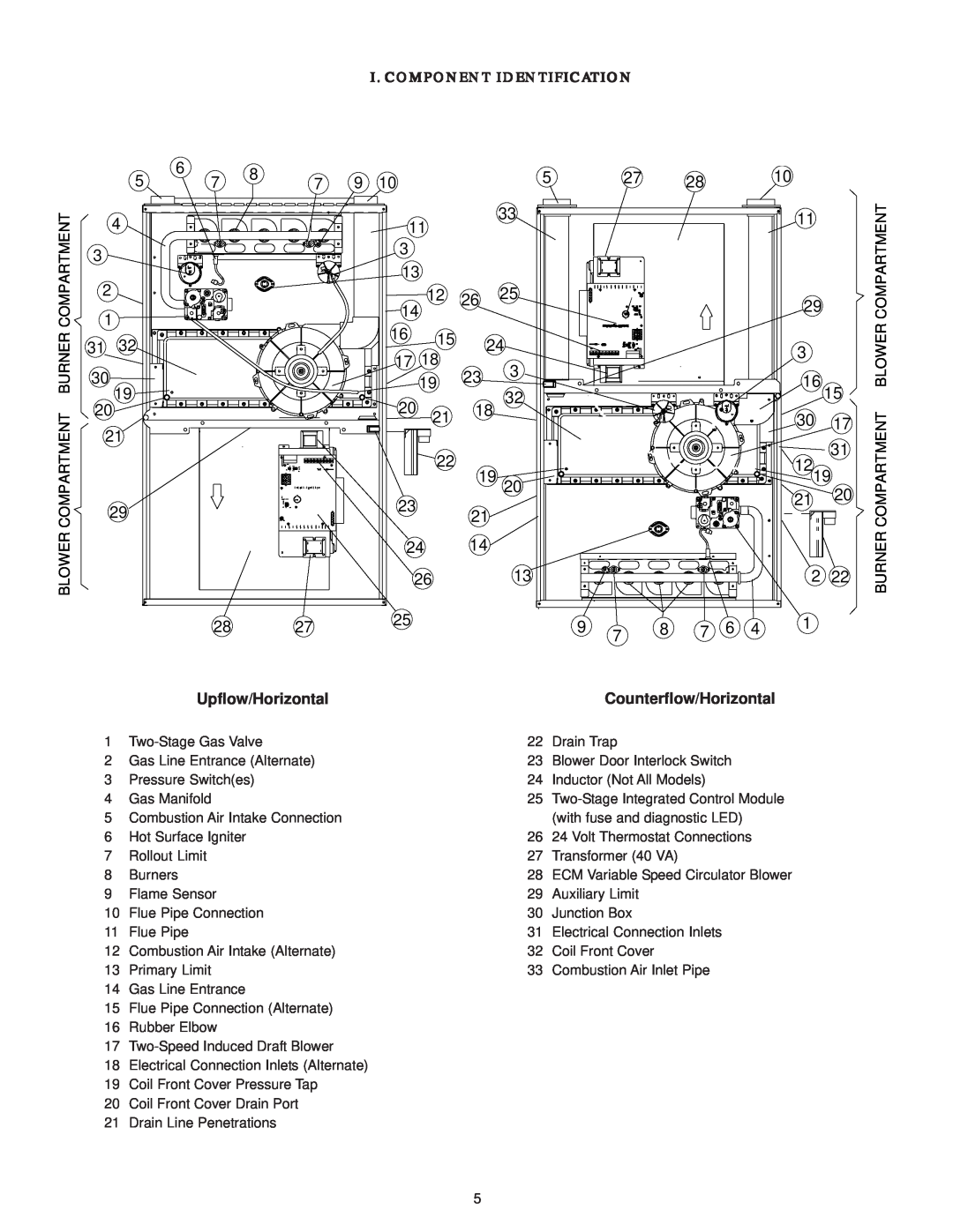
I. COMPONENT IDENTIFICATION
BLOWER COMPARTMENT BURNER COMPARTMENT
5
4
3
2
1
31 32
30
19
20
21
29
6 | 7 | 8 | 7 | 9 | 10 |
|
| 5 | 27 | 28 | 10 |
|
|
|
|
| |||||||||
|
|
|
|
| 11 |
|
| 33 |
|
| 11 |
|
|
|
|
|
|
|
|
|
|
|
|
| |
|
|
|
|
| 3 |
|
|
|
|
|
|
|
|
|
|
|
| 13 | 12 | 26 | 25 |
|
|
|
|
* | * |
|
|
|
|
|
|
|
| |||
* | * | * |
|
|
|
|
|
|
|
|
|
|
| * |
|
|
|
|
|
|
|
|
| 29 |
|
* | * | * |
|
| 14 |
|
|
|
|
|
| |
|
|
|
|
| 16 | 15 | 24 |
|
| 3 |
| |
|
|
|
|
| 17 18 |
|
|
| ||||
|
|
|
|
|
| 3 |
|
|
| |||
|
|
|
|
| 23 |
|
| 16 |
| |||
|
|
|
|
| 19 |
|
|
| ||||
|
|
|
|
| 32 |
|
| 15 | ||||
|
|
|
|
| 18 |
|
| |||||
|
|
|
|
| 20 | 21 |
|
| 30 | 17 | ||
|
|
|
|
|
|
|
|
|
| |||
|
|
|
|
|
| 22 |
|
|
|
|
| 31 |
|
|
|
|
|
| 19 |
|
|
| 1219 | ||
|
|
|
|
|
|
| 20 |
|
| |||
|
|
| W R |
|
|
|
|
|
| 21 | 20 | |
|
|
|
|
|
|
|
|
|
|
|
| |
|
|
|
|
| 23 |
| 21 |
|
|
|
|
|
|
|
|
|
|
|
|
|
|
|
|
| |
2414
|
| 26 | 13 |
|
|
|
|
|
| 2 | 22 |
28 | 27 | 25 |
| 9 | 7 | 8 | 7 | 6 | 4 | 1 |
|
|
|
|
|
BURNER COMPARTMENT BLOWER COMPARTMENT
| Upflow/Horizontal |
| Counterflow/Horizontal |
1 | 22 | Drain Trap | |
2 | Gas Line Entrance (Alternate) | 23 | Blower Door Interlock Switch |
3 | Pressure Switch(es) | 24 | Inductor (Not All Models) |
4 | Gas Manifold | 25 | |
5 | Combustion Air Intake Connection |
| (with fuse and diagnostic LED) |
6 | Hot Surface Igniter | 26 | 24 Volt Thermostat Connections |
7 | Rollout Limit | 27 | Transformer (40 VA) |
8 | Burners | 28 | ECM Variable Speed Circulator Blower |
9 | Flame Sensor | 29 | Auxiliary Limit |
10 | Flue Pipe Connection | 30 | Junction Box |
11 | Flue Pipe | 31 | Electrical Connection Inlets |
12 | Combustion Air Intake (Alternate) | 32 | Coil Front Cover |
13 | Primary Limit | 33 | Combustion Air Inlet Pipe |
14Gas Line Entrance
15Flue Pipe Connection (Alternate)
16Rubber Elbow
17
18Electrical Connection Inlets (Alternate)
19Coil Front Cover Pressure Tap
20Coil Front Cover Drain Port
21Drain Line Penetrations
5