STANDARD | * | * | * | ALTERNATE |
| * |
| ||
|
| * |
|
|
JUNCTION BOX | * |
|
| JUNCTION BOX |
* | * | * | ||
LOCATION |
|
|
| LOCATION |
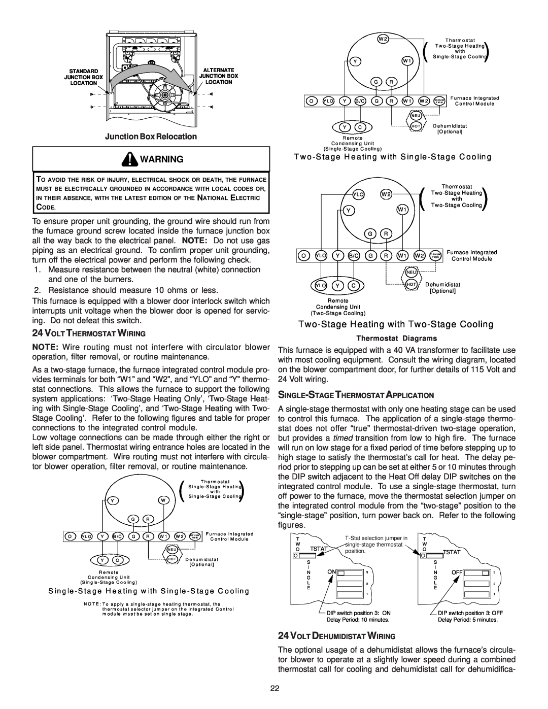
Junction Box Relocation
![]() WARNING
WARNING
TO AVOID THE RISK OF INJURY, ELECTRICAL SHOCK OR DEATH, THE FURNACE MUST BE ELECTRICALLY GROUNDED IN ACCORDANCE WITH LOCAL CODES OR, IN THEIR ABSENCE, WITH THE LATEST EDITION OF THE NATIONAL ELECTRIC CODE.
To ensure proper unit grounding, the ground wire should run from the furnace ground screw located inside the furnace junction box all the way back to the electrical panel. NOTE: Do not use gas piping as an electrical ground. To confirm proper unit grounding, turn off the electrical power and perform the following check.
1.Measure resistance between the neutral (white) connection and one of the burners.
2.Resistance should measure 10 ohms or less.
This furnace is equipped with a blower door interlock switch which interrupts unit voltage when the blower door is opened for servic- ing. Do not defeat this switch.
24 VOLT THERMOSTAT WIRING
NOTE: Wire routing must not interfere with circulator blower operation, filter removal, or routine maintenance.
As a
Low voltage connections can be made through either the right or left side panel. Thermostat wiring entrance holes are located in the blower compartment. Wire routing must not interfere with circula- tor blower operation, filter removal, or routine maintenance.
W 2 | ( | T herm o stat |
| Tw o | |
| w ith | |
| S ingle |
YW 1
G R
O | Y L O Y B /C | G | R W 1 W 2 | D E HU M F urnac e In tegrated | ||
T W IN | C ontro l M odule | |||||
|
|
|
|
|
| |
|
|
|
| N E U |
|
|
| Y | C |
| H O T | D ehum idistat | |
|
|
|
|
| [O ptiona l] | |
R em ote
C o nd ens ing U nit
(S ingle
T w o
|
|
|
| ( |
| Thermostat |
|
| YLO | W 2 | |||
|
| Y | W1 | |||
|
| G | R |
|
|
|
O YLO | Y | B/C G | R W1 | W 2 | D EHUM Furnace Integrated | |
T W IN | Control Module | |||||
|
|
|
|
|
| |
|
|
|
| NE U |
|
|
YLO | Y | C |
| HO T Dehumidistat | ||
|
|
|
|
| [Optional] | |
Remote
Condensing Unit
Two-Stage Heating with Two-Stage Cooling
Thermostat Diagrams
This furnace is equipped with a 40 VA transformer to facilitate use with most cooling equipment. Consult the wiring diagram, located on the blower compartment door, for further details of 115 Volt and 24 Volt wiring.
SINGLE-STAGE THERMOSTAT APPLICATION
A
(
YW
G R
O Y L O Y B /C G R W 1 W 2
N E U
T h e rm o s ta t ) S in g le - S ta g e H e a tin g
w ith
S in g le - S ta g e C o o lin g
D E H U M F u rn a c e In te g ra te d
T W IN | C o n tro l M o d u le |
the DIP switch adjacent to the Heat Off delay DIP switches on the integrated control module. To use a
T |
| T |
| |
W | TSTAT | W |
| |
O | position. | O | TSTAT | |
|
|
|
Y | C | H O T | D e h u m id is ta t |
|
|
| [O p tio n a l] |
R e m o te
C o n d e n s in g U n it
(S in g le - S ta g e C o o lin g )
S in g le - S ta g e H e a tin g w ith S in g le - S ta g e C o o lin g
N O T E : T o a p p ly a s in g le - s ta g e h e a tin g th e rm o s ta t, th e
th e rm o s ta t s e le c to r ju m p e r o n th e in te g ra te d C o n tro l m o d u le m u s t b e s e t o n s in g le s ta g e .
S |
|
| S |
|
|
I | ON |
| I | OFF |
|
N | 3 | N | 3 | ||
G |
|
| G |
|
|
L |
| 2 | L |
| 2 |
E |
|
| E |
|
|
|
| 1 |
|
| 1 |
| DIP switch position 3: ON |
| DIP switch position 3: OFF | ||
| Delay Period: 10 minutes. |
| Delay Period: 5 minutes. | ||
24 VOLT DEHUMIDISTAT WIRING
The optional usage of a dehumidistat allows the furnace’s circula- tor blower to operate at a slightly lower speed during a combined thermostat call for cooling and dehumidistat call for dehumidifica-
22