|
|
| 8 | 7 | 6 | 5 |
| 4 | 3 | 2 | 1 |
|
| |||
Cooling |
|
|
|
|
|
|
|
|
|
|
|
|
|
|
|
|
|
|
|
|
|
|
|
|
|
|
|
|
|
|
|
| |
Speed |
|
|
|
|
|
|
|
|
|
|
|
|
|
|
|
|
|
|
|
|
|
|
|
|
|
|
|
|
|
| |||
Tap A |
|
|
|
|
|
|
|
|
|
|
| O O | ||||
|
|
|
|
|
|
|
|
|
|
|
| F |
| F | ||
|
|
|
|
|
|
|
|
|
|
|
| F |
| F | ||
Cooling |
|
| 8 | 7 | 6 | 5 |
| 4 | 3 | 2 | 1 |
|
| |||
|
|
|
|
|
|
|
|
|
|
|
|
|
|
|
| |
Speed |
|
|
|
|
|
|
|
|
|
|
|
|
|
|
|
|
|
|
|
|
|
|
|
|
|
|
|
|
|
|
|
| |
Tap B |
|
|
|
|
|
|
|
|
|
|
|
|
|
|
|
|
|
|
|
|
|
|
|
|
|
|
|
|
|
|
|
| |
|
|
|
|
|
|
|
|
|
|
| O O | |||||
|
|
|
|
|
|
|
|
|
|
|
| |||||
|
|
|
|
|
|
|
|
|
|
|
| F N | ||||
|
|
|
|
|
|
|
|
|
|
|
| F |
|
|
|
|
Cooling |
|
| 8 | 7 | 6 | 5 |
| 4 | 3 | 2 | 1 |
|
| |||
|
|
|
|
|
|
|
|
|
|
|
|
|
|
|
| |
Speed |
|
|
|
|
|
|
|
|
|
|
|
|
|
|
|
|
|
|
|
|
|
|
|
|
|
|
|
|
|
|
|
| |
Tap C |
|
|
|
|
|
|
|
|
|
|
|
|
|
|
|
|
|
|
|
|
|
|
|
|
|
|
|
|
|
|
|
| |
|
|
|
|
|
|
|
|
|
|
| O O | |||||
|
|
|
|
|
|
|
|
|
|
|
| |||||
|
|
|
|
|
|
|
|
|
|
|
| N F | ||||
|
|
|
|
|
|
|
|
|
|
|
|
|
| F | ||
Cooling * |
|
| 8 | 7 | 6 | 5 |
| 4 | 3 | 2 | 1 |
|
| |||
|
|
|
|
|
|
|
|
|
|
|
|
|
|
|
| |
Speed |
|
|
|
|
|
|
|
|
|
|
|
|
|
|
|
|
|
|
|
|
|
|
|
|
|
|
|
|
|
|
|
| |
Tap D |
|
|
|
|
|
|
|
|
|
|
|
|
|
|
|
|
|
|
|
|
|
|
|
|
|
|
|
|
|
|
|
| |
|
|
|
|
|
|
|
|
|
|
| O O | |||||
|
|
|
|
|
|
|
|
|
|
|
| |||||
|
|
|
|
|
|
|
|
|
|
|
| N N | ||||
|
|
|
|
|
|
|
|
|
|
|
|
|
|
|
|
|
|
|
|
|
|
|
|
|
|
|
|
|
|
|
|
|
|
Cooling Speed Taps |
|
|
|
|
|
|
| |||||||||
(* indicates factory setting) |
|
|
|
|
|
| ||||||||||
8 7 6 5 4 3 2 1
Normal*
O O
F F
F F
8 7 6 5 4 3 2 1
+ (Plus) Adjust
O O
F N
F
8 7 6 5 4 3 2 1
- (Minus) Adjust
O O
N F
F
Adjust Taps
(* indicates factory setting)
| 8 | 7 |
| 6 | 5 |
| 4 | 3 | 2 | 1 |
|
| ||
Heating |
|
|
|
|
|
|
|
|
|
|
|
|
|
|
|
|
|
|
|
|
|
|
|
|
|
|
|
| |
Speed |
|
|
|
|
|
|
|
|
|
|
|
|
|
|
|
|
|
|
|
|
|
|
|
|
|
|
|
| |
Tap A | O O |
|
|
|
|
|
|
|
|
|
| |||
| F |
| F |
|
|
|
|
|
|
|
|
|
| |
| F |
| F |
|
|
|
|
|
|
|
|
|
| |
Heating * | 8 | 7 |
| 6 | 5 |
| 4 | 3 | 2 | 1 |
|
| ||
|
|
|
|
|
|
|
|
|
|
|
|
|
| |
Speed |
|
|
|
|
|
|
|
|
|
|
|
|
|
|
|
|
|
|
|
|
|
|
|
|
|
|
|
| |
Tap B |
|
|
|
|
|
|
|
|
|
|
|
|
|
|
|
|
|
|
|
|
|
|
|
|
|
|
|
| |
O O |
|
|
|
|
|
|
|
|
|
| ||||
|
|
|
|
|
|
|
|
|
|
| ||||
| F N |
|
|
|
|
|
|
|
|
|
| |||
| F |
|
|
|
|
|
|
|
|
|
|
|
|
|
Heating | 8 | 7 |
| 6 | 5 |
| 4 | 3 | 2 | 1 |
|
| ||
|
|
|
|
|
|
|
|
|
|
|
|
|
| |
Speed |
|
|
|
|
|
|
|
|
|
|
|
|
|
|
|
|
|
|
|
|
|
|
|
|
|
|
|
| |
Tap C |
|
|
|
|
|
|
|
|
|
|
|
|
|
|
|
|
|
|
|
|
|
|
|
|
|
|
|
| |
O O |
|
|
|
|
|
|
|
|
|
| ||||
|
|
|
|
|
|
|
|
|
|
| ||||
| N F |
|
|
|
|
|
|
|
|
|
| |||
|
|
| F |
|
|
|
|
|
|
|
|
|
| |
Heating | 8 | 7 |
| 6 | 5 |
| 4 | 3 | 2 | 1 |
|
| ||
|
|
|
|
|
|
|
|
|
|
|
|
|
| |
Speed |
|
|
|
|
|
|
|
|
|
|
|
|
|
|
|
|
|
|
|
|
|
|
|
|
|
|
|
| |
Tap D |
|
|
|
|
|
|
|
|
|
|
|
|
|
|
|
|
|
|
|
|
|
|
|
|
|
|
|
| |
O O |
|
|
|
|
|
|
|
|
|
| ||||
|
|
|
|
|
|
|
|
|
|
| ||||
| N N |
|
|
|
|
|
|
|
|
|
| |||
|
|
|
|
|
|
|
|
|
|
|
|
|
|
|
Heating Speed Taps
(* indicates factory setting)
| 100% CFM | 100% CFM |
OFF | 50% CFM | OFF |
| 1/2 min | 1 min |
Cooling Demand
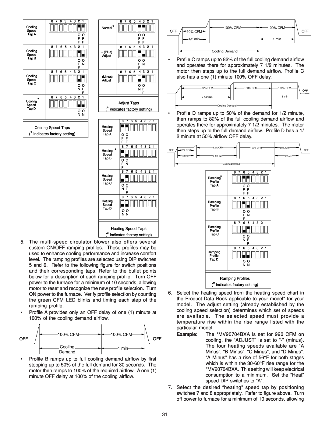
•Profile C ramps up to 82% of the full cooling demand airflow and operates there for approximately 7 1/2 minutes. The motor then steps up to the full demand airflow. Profile C also has a one (1) minute 100% OFF delay.
![]() 82% CFM
82% CFM![]()
![]() 100% CFM
100% CFM![]() 100% CFM
100% CFM
OFF
7 1/2 min |
|
|
| 1 min |
|
|
|
| |||
|
|
|
|
|
|
Cooling Demand
•Profile D ramps up to 50% of the demand for 1/2 minute, then ramps to 82% of the full cooling demand airflow and operates there for approximately 7 1/2 minutes. The motor then steps up to the full demand airflow. Profile D has a 1/ 2 minute at 50% airflow OFF delay.
|
|
|
|
|
|
|
|
|
|
|
| 82% CFM |
|
|
|
|
|
|
|
|
|
| 100% CFM |
|
|
|
|
| 50% CFM |
|
|
| ||||
|
|
|
|
|
|
|
|
|
|
|
|
|
|
|
|
|
|
|
|
|
|
|
|
|
|
|
|
|
| |||||||
OFF |
|
| 50% CFM |
|
|
|
|
|
|
|
|
|
|
|
|
|
|
|
|
|
|
|
|
|
|
|
|
|
|
|
|
|
| OFF | ||
|
|
|
|
|
|
|
|
|
|
|
|
|
|
|
|
|
|
|
|
|
|
|
|
|
|
|
|
|
| |||||||
|
|
|
|
|
|
|
|
|
|
|
|
|
|
|
|
|
|
|
|
|
|
|
|
|
|
|
| |||||||||
|
|
|
|
|
|
|
|
|
|
|
|
|
|
|
|
|
|
|
|
|
|
|
|
|
|
|
|
|
|
|
|
|
|
| ||
|
|
|
|
|
|
|
|
|
|
|
|
|
|
|
|
|
|
|
|
|
|
|
|
|
|
|
|
|
|
|
|
|
|
|
|
|
|
|
|
| 1/2 min |
|
|
|
|
|
| 7 1/2 min |
|
|
|
|
|
|
|
|
|
|
|
|
|
|
|
|
|
|
|
| 1/2 min |
|
| ||
|
|
|
| Cooling Demand |
|
|
|
|
|
|
|
|
|
|
|
|
|
|
|
| ||||||||||||||||
|
|
|
|
|
|
|
|
|
|
|
|
|
|
|
|
|
|
|
| |||||||||||||||||
|
|
|
|
|
|
|
|
|
|
|
|
|
|
|
|
|
|
|
|
|
|
|
|
|
|
|
|
|
|
| ||||||
|
|
|
|
|
|
|
|
|
|
|
|
|
|
|
|
|
|
|
|
|
|
|
|
|
|
|
|
|
|
| ||||||
|
|
|
|
|
|
|
|
|
|
|
|
|
|
|
|
|
|
|
|
|
|
|
|
|
|
|
|
|
|
|
| |||||
|
|
|
|
|
|
|
|
| 8 | 7 | 6 | 5 |
| 4 | 3 | 2 | 1 |
|
|
|
|
|
|
| ||||||||||||
|
|
|
|
|
|
|
|
|
| Ramping* |
|
|
|
|
|
|
|
|
|
|
|
|
|
|
|
|
|
|
|
|
|
| ||||
|
|
|
|
|
|
|
|
|
|
|
|
|
|
|
|
|
|
|
|
|
|
|
|
|
|
|
|
|
|
|
| |||||
|
|
|
|
|
|
|
|
|
|
|
|
|
|
|
|
|
|
|
|
|
|
|
|
|
|
|
|
|
|
|
| |||||
|
|
|
|
|
|
|
|
|
| Profile |
|
|
|
|
|
|
|
|
|
|
|
|
|
|
|
|
|
|
|
|
|
| ||||
|
|
|
|
|
|
|
|
|
|
|
|
|
|
|
|
|
|
|
|
|
|
|
|
|
|
|
|
|
|
|
| |||||
|
|
|
|
|
|
|
|
|
| Tap A |
|
|
|
|
| O O |
|
|
|
|
|
|
|
|
|
|
|
|
| |||||||
|
|
|
|
|
|
|
|
|
|
|
|
|
|
|
|
|
|
|
| F F |
|
|
|
|
|
|
|
|
|
|
|
|
| |||
|
|
|
|
|
|
|
|
|
|
|
|
|
|
|
|
|
|
|
| F F |
|
|
|
|
|
|
|
|
|
|
|
|
| |||
8 7 6 5 4 3 2 1
Ramping
Profile
Tap B
O O
F N
F
8 7 6 5 4 3 2 1
Ramping
Profile
Tap CO O
5. The |
custom ON/OFF ramping profiles. These profiles may be |
used to enhance cooling performance and increase comfort |
N F
F
8 7 6 5 4 3 2 1
Ramping
Profile
level. The ramping profiles are selected using DIP switches |
5 and 6. Refer to the following figure for switch positions |
and their corresponding taps. Refer to the bullet points |
below for a description of each ramping profile. Turn OFF |
Tap D
O O N N
power to the furnace for a minimum of 10 seconds, allowing |
motor to reset and recognize the new profile selection. Turn |
ON power to the furnace. Verify profile selection by counting |
the green CFM LED blinks and timing each step of the |
ramping profile. |
•Profile A provides only an OFF delay of one (1) minute at 100% of the cooling demand airflow.
100% CFM | 100% CFM |
OFF | OFF |
![]() Cooling
Cooling ![]()
![]() 1 min
1 min![]()
Demand
•Profile B ramps up to full cooling demand airflow by first stepping up to 50% of the full demand for 30 seconds. The motor then ramps to 100% of the required airflow. A one (1) minute OFF delay at 100% of the cooling airflow.
Ramping Profiles
(* indicates factory setting)
6.Select the heating speed from the heating speed chart in the Product Data Book applicable to your model* for your model. The adjust setting (already established by the cooling speed selection) determines which set of speeds are available. The selected speed must provide a temperature rise within the rise range listed with the particular model.
Example: The *MV90704BXA is set for 990 CFM on cooling, the “ADJUST” is set to
7.Select the desired “heating” speed tap by positioning switches 7 and 8 appropriately. Refer to figure above. Turn off power to furnace for a minimum of 10 seconds, allowing
31