Corrections must be in accordance with the latest edition of the National Fuel Gas Code NFPA 54/ANSI Z223.1 and/or CSA B149 Installation Codes.
If resizing is required on any portion of the venting system, use the appropriate table in Appendix G in the latest edition of the National Fuel Gas Code ANSI Z223.1 and/or CSA B149 Installation Codes.
THERMOSTAT LOCATION
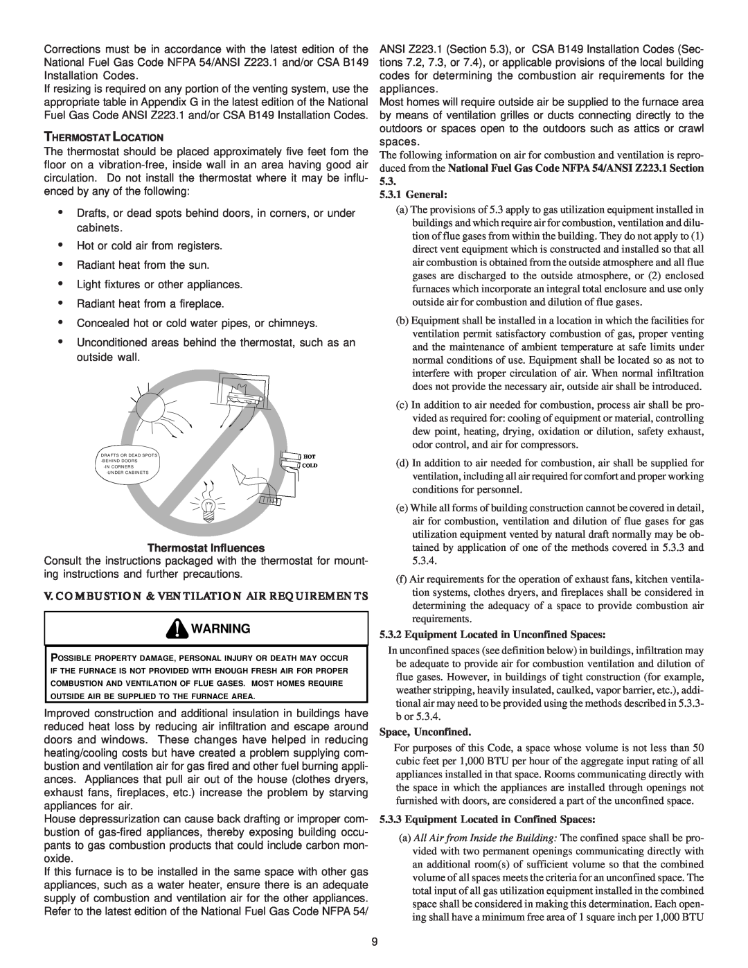
The thermostat should be placed approximately five feet fom the floor on a
•Drafts, or dead spots behind doors, in corners, or under cabinets.
•Hot or cold air from registers.
•Radiant heat from the sun.
•Light fixtures or other appliances.
•Radiant heat from a fireplace.
•Concealed hot or cold water pipes, or chimneys.
•Unconditioned areas behind the thermostat, such as an outside wall.
DRAFTS OR DEAD SPOTS | HOT |
COLD | |
|
Thermostat Influences
Consult the instructions packaged with the thermostat for mount- ing instructions and further precautions.
V. COMBUSTION & VENTILATION AIR REQUIREMENTS
![]() WARNING
WARNING
POSSIBLE PROPERTY DAMAGE, PERSONAL INJURY OR DEATH MAY OCCUR IF THE FURNACE IS NOT PROVIDED WITH ENOUGH FRESH AIR FOR PROPER COMBUSTION AND VENTILATION OF FLUE GASES. MOST HOMES REQUIRE OUTSIDE AIR BE SUPPLIED TO THE FURNACE AREA.
Improved construction and additional insulation in buildings have reduced heat loss by reducing air infiltration and escape around doors and windows. These changes have helped in reducing heating/cooling costs but have created a problem supplying com- bustion and ventilation air for gas fired and other fuel burning appli- ances. Appliances that pull air out of the house (clothes dryers, exhaust fans, fireplaces, etc.) increase the problem by starving appliances for air.
House depressurization can cause back drafting or improper com- bustion of
If this furnace is to be installed in the same space with other gas appliances, such as a water heater, ensure there is an adequate supply of combustion and ventilation air for the other appliances. Refer to the latest edition of the National Fuel Gas Code NFPA 54/
ANSI Z223.1 (Section 5.3), or CSA B149 Installation Codes (Sec- tions 7.2, 7.3, or 7.4), or applicable provisions of the local building codes for determining the combustion air requirements for the appliances.
Most homes will require outside air be supplied to the furnace area by means of ventilation grilles or ducts connecting directly to the outdoors or spaces open to the outdoors such as attics or crawl spaces.
The following information on air for combustion and ventilation is repro- duced from the National Fuel Gas Code NFPA 54/ANSI Z223.1 Section 5.3.
5.3.1General:
(a)The provisions of 5.3 apply to gas utilization equipment installed in buildings and which require air for combustion, ventilation and dilu- tion of flue gases from within the building. They do not apply to (1) direct vent equipment which is constructed and installed so that all air combustion is obtained from the outside atmosphere and all flue gases are discharged to the outside atmosphere, or (2) enclosed furnaces which incorporate an integral total enclosure and use only outside air for combustion and dilution of flue gases.
(b)Equipment shall be installed in a location in which the facilities for ventilation permit satisfactory combustion of gas, proper venting and the maintenance of ambient temperature at safe limits under normal conditions of use. Equipment shall be located so as not to interfere with proper circulation of air. When normal infiltration does not provide the necessary air, outside air shall be introduced.
(c)In addition to air needed for combustion, process air shall be pro- vided as required for: cooling of equipment or material, controlling dew point, heating, drying, oxidation or dilution, safety exhaust, odor control, and air for compressors.
(d)In addition to air needed for combustion, air shall be supplied for ventilation, including all air required for comfort and proper working conditions for personnel.
(e)While all forms of building construction cannot be covered in detail, air for combustion, ventilation and dilution of flue gases for gas utilization equipment vented by natural draft normally may be ob- tained by application of one of the methods covered in 5.3.3 and 5.3.4.
(f)Air requirements for the operation of exhaust fans, kitchen ventila- tion systems, clothes dryers, and fireplaces shall be considered in determining the adequacy of a space to provide combustion air requirements.
5.3.2Equipment Located in Unconfined Spaces:
In unconfined spaces (see definition below) in buildings, infiltration may be adequate to provide air for combustion ventilation and dilution of flue gases. However, in buildings of tight construction (for example, weather stripping, heavily insulated, caulked, vapor barrier, etc.), addi- tional air may need to be provided using the methods described in 5.3.3- b or 5.3.4.
Space, Unconfined.
For purposes of this Code, a space whose volume is not less than 50 cubic feet per 1,000 BTU per hour of the aggregate input rating of all appliances installed in that space. Rooms communicating directly with the space in which the appliances are installed through openings not furnished with doors, are considered a part of the unconfined space.
5.3.3Equipment Located in Confined Spaces:
(a)All Air from Inside the Building: The confined space shall be pro- vided with two permanent openings communicating directly with an additional room(s) of sufficient volume so that the combined volume of all spaces meets the criteria for an unconfined space. The total input of all gas utilization equipment installed in the combined space shall be considered in making this determination. Each open- ing shall have a minimum free area of 1 square inch per 1,000 BTU
9
