gas. Do not rely on your sense of smell. Contact a local propane gas supplier about installing a gas detecting warning system. If the presence of gas is suspected, follow the instructions on Page 4 of this manual.
All propane gas equipment must conform to the safety standards of the National Board of Fire Underwriters, NBFU Manual 58.
For satisfactory operation, propane gas pressure must be 11 inch w.c. at the furnace manifold with all gas appliances in operation. Maintaining proper gas pressure depends on three main factors:
1.Vaporization rate, depending on temperature of the liquid, and “wetted surface” area of the container or containers.
2.Proper pressure regulation.
3.Pressure drop in lines between regulators, and between second stage regulator and the appliance. Pipe size will depend on length of pipe run and total load of all appliances.
Complete information regarding tank sizing for vaporization, rec- ommended regulator settings, and pipe sizing is available from most regulator manufacturers and propane gas suppliers.
Since propane gas will quickly dissolve white lead and most stan- dard commercial compounds, special pipe dope must be used.
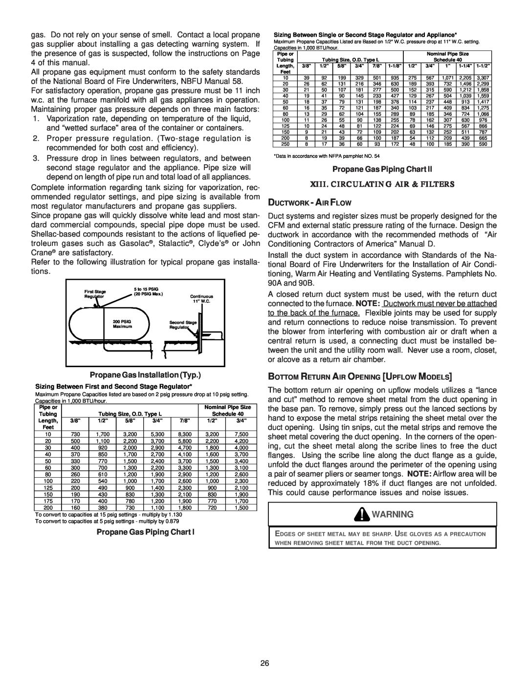
Refer to the following illustration for typical propane gas installa- tions.
First Stage | 5 to 15 PSIG |
|
|
| ||
(20 PSIG Max.) | Continuous | |||||
Regulator | ||||||
|
|
| 11" W.C. | |||
200 PSIG |
|
| Second Stage |
| ||
Maximum |
|
| Regulator |
| ||
|
|
|
|
|
| |
|
|
|
|
|
| |
Propane Gas Installation (Typ.)
Sizing Between First and Second Stage Regulator*
Maximum Propane Capacities listed are based on 2 psig pressure drop at 10 psig setting. Capacities in 1,000 BTU/hour.
Pipe or |
|
|
|
|
| Nominal Pipe Size | |
Tubing |
| Tubing Size, O.D. Type L |
| Schedule 40 | |||
Length, | 3/8" | 1/2" | 5/8" | 3/4" | 7/8" | 1/2" | 3/4" |
Feet |
|
|
|
|
|
|
|
10 | 730 | 1,700 | 3,200 | 5,300 | 8,300 | 3,200 | 7,500 |
20 | 500 | 1,100 | 2,200 | 3,700 | 5,800 | 2,200 | 4,200 |
30 | 400 | 920 | 2,000 | 2,900 | 4,700 | 1,800 | 4,000 |
40 | 370 | 850 | 1,700 | 2,700 | 4,100 | 1,600 | 3,700 |
50 | 330 | 770 | 1,500 | 2,400 | 3,700 | 1,500 | 3,400 |
60 | 300 | 700 | 1,300 | 2,200 | 3,300 | 1,300 | 3,100 |
80 | 260 | 610 | 1,200 | 1,900 | 2,900 | 1,200 | 2,600 |
100 | 220 | 540 | 1,000 | 1,700 | 2,600 | 1,000 | 2,300 |
125 | 200 | 490 | 900 | 1,400 | 2,300 | 900 | 2,100 |
150 | 190 | 430 | 830 | 1,300 | 2,100 | 830 | 1,900 |
175 | 170 | 400 | 780 | 1,200 | 1,900 | 770 | 1,700 |
200 | 160 | 380 | 730 | 1,100 | 1,800 | 720 | 1,500 |
To convert to capacities at 15 psig settings - multiply by 1.130
To convert to capacities at 5 psig settings - multiply by 0.879
Propane Gas Piping Chart I
Sizing Between Single or Second Stage Regulator and Appliance*
Maximum Propane Capacities Listed are Based on 1/2" W.C. pressure drop at 11" W.C. setting. Capacities in 1,000 BTU/hour.
Pipe or |
|
|
|
|
|
|
| Nominal Pipe Size |
| ||
Tubing |
| Tubing Size, O.D. Type L |
|
| Schedule 40 |
| |||||
Length, | 3/8" | 1/2" | 5/8" | 3/4" | 7/8" | 1/2" | 3/4" | 1" | |||
Feet |
|
|
|
|
|
|
|
|
|
|
|
10 | 39 | 92 | 199 | 329 | 501 | 935 | 275 | 567 | 1,071 | 2,205 | 3,307 |
20 | 26 | 62 | 131 | 216 | 346 | 630 | 189 | 393 | 732 | 1,496 | 2,299 |
30 | 21 | 50 | 107 | 181 | 277 | 500 | 152 | 315 | 590 | 1,212 | 1,858 |
40 | 19 | 41 | 90 | 145 | 233 | 427 | 129 | 267 | 504 | 1,039 | 1,559 |
50 | 18 | 37 | 79 | 131 | 198 | 376 | 114 | 237 | 448 | 913 | 1,417 |
60 | 16 | 35 | 72 | 121 | 187 | 340 | 103 | 217 | 409 | 834 | 1,275 |
80 | 13 | 29 | 62 | 104 | 155 | 289 | 89 | 185 | 346 | 724 | 1,066 |
100 | 11 | 26 | 55 | 90 | 138 | 255 | 78 | 162 | 307 | 630 | 976 |
125 | 10 | 24 | 48 | 81 | 122 | 224 | 69 | 146 | 275 | 567 | 866 |
150 | 9 | 21 | 43 | 72 | 109 | 202 | 63 | 132 | 252 | 511 | 787 |
200 | 8 | 19 | 39 | 66 | 100 | 187 | 54 | 112 | 209 | 439 | 665 |
250 | 8 | 17 | 36 | 60 | 93 | 172 | 48 | 100 | 185 | 390 | 590 |
*Data in accordance with NFPA pamphlet NO. 54
Propane Gas Piping Chart II
XIII. CIRCULATING AIR & FILTERS
DUCTWORK - AIR FLOW
Duct systems and register sizes must be properly designed for the CFM and external static pressure rating of the furnace. Design the ductwork in accordance with the recommended methods of “Air Conditioning Contractors of America” Manual D.
Install the duct system in accordance with Standards of the Na- tional Board of Fire Underwriters for the Installation of Air Condi- tioning, Warm Air Heating and Ventilating Systems. Pamphlets No. 90A and 90B.
A closed return duct system must be used, with the return duct connected to the furnace. NOTE: Ductwork must never be attached to the back of the furnace. Flexible joints may be used for supply and return connections to reduce noise transmission. To prevent the blower from interfering with combustion air or draft when a central return is used, a connecting duct must be installed be- tween the unit and the utility room wall. Never use a room, closet, or alcove as a return air chamber.
BOTTOM RETURN AIR OPENING [UPFLOW MODELS]
The bottom return air opening on upflow models utilizes a “lance and cut” method to remove sheet metal from the duct opening in the base pan. To remove, simply press out the lanced sections by hand to expose the metal strips retaining the sheet metal over the duct opening. Using tin snips, cut the metal strips and remove the sheet metal covering the duct opening. In the corners of the open- ing, cut the sheet metal along the scribe lines to free the duct flanges. Using the scribe line along the duct flange as a guide, unfold the duct flanges around the perimeter of the opening using a pair of seamer pliers or seamer tongs. NOTE: Airflow area will be reduced by approximately 18% if duct flanges are not unfolded. This could cause performance issues and noise issues.
![]() WARNING
WARNING
EDGES OF SHEET METAL MAY BE SHARP. USE GLOVES AS A PRECAUTION WHEN REMOVING SHEET METAL FROM THE DUCT OPENING.
26