90º
MEDIUM RADIUS
ELBOWS
12" MIN.
TO ROOF OR
HIGHEST
ANTICIPATED
SNOW LEVEL
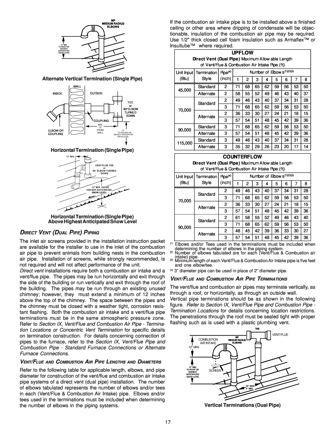
Alternate Vertical Termination (Single Pipe)
If the combustion air intake pipe is to be installed above a finished ceiling or other area where dripping of condensate will be objec- tionable, insulation of the combustion air pipe may be required. Use 1/2” thick closed cell foam insulation such as Armaflex™ or Insultube™ where required.
UPFLOW
Direct Vent (Dual Pipe) Maximum Allow able Length
of Vent/Flue & Combustion Air Intake Pipe (ft)
Unit Input | Termination | Pipe(4) |
|
| Number of Elbow s(1)(2)(3) |
|
| |||||
(Btu) | Style | (inch) | 1 | 2 |
| 3 | 4 | 5 | 6 |
| 7 | 8 |
INSIDE
ELBOW OR COUPLING
WALL |
OUTSIDE
TEE or
90°ELBOW
TURNED
DOWN
COUPLING
|
|
|
|
|
|
MIN. |
|
|
|
| |
12" |
|
|
|
|
|
FROM |
|
| 12" |
| |
WALL |
|
| TO | GROUND OR | |
|
| HIGHEST ANTICIPATED | |||
|
|
| SNOW LEVEL | ||
45,000 | Standard | 2 | 71 | 68 | 65 | 62 | 59 | 56 | 53 | 50 | |
Alternate | 2 | 58 | 55 | 52 | 49 | 46 | 43 | 40 | 37 | ||
| |||||||||||
| Standard | 2 | 49 | 46 | 43 | 40 | 37 | 34 | 31 | 28 | |
70,000 | 3 | 71 | 68 | 65 | 62 | 59 | 56 | 53 | 50 | ||
| |||||||||||
Alternate | 2 | 36 | 33 | 30 | 27 | 24 | 21 | 18 | 15 | ||
| |||||||||||
| 3 | 57 | 54 | 51 | 48 | 45 | 42 | 39 | 36 | ||
|
| ||||||||||
90,000 | Standard | 3 | 71 | 68 | 65 | 62 | 59 | 56 | 53 | 50 | |
Alternate | 3 | 57 | 54 | 51 | 48 | 45 | 42 | 39 | 36 | ||
| |||||||||||
115,000 | Standard | 3 | 49 | 46 | 43 | 40 | 37 | 34 | 31 | 28 | |
Alternate | 3 | 35 | 32 | 29 | 26 | 23 | 20 | 17 | 14 | ||
|
Horizontal Termination (Single Pipe)
12" MIN.
VENT/FLUE TEE
or
90° ELBOW TURNED
DOWN
Horizontal Termination (Single Pipe)
Above Highest Anticipated Snow Level
DIRECT VENT (DUAL PIPE) PIPING
The inlet air screens provided in the installation instruction packet are available for the installer to use in the inlet of the combustion air pipe to prevent animals from building nests in the combustion air pipe. Installation of screens, while strongly recommended, is not required and will not affect performance of the unit.
Direct vent installations require both a combustion air intake and a vent/flue pipe. The pipes may be run horizontally and exit through the side of the building or run vertically and exit through the roof of the building. The pipes may be run through an existing unused chimney; however, they must extend a minimum of 12 inches above the top of the chimney. The space between the pipes and the chimney must be closed with a weather tight, corrosion resis- tant flashing. Both the combustion air intake and a vent/flue pipe terminations must be in the same atmospheric pressure zone. Refer to Section IX, Vent/Flue and Combustion Air Pipe - Termina- tion Locations or Concentric Vent Termination for specific details on termination construction. For details concerning connection of pipes to the furnace, refer to the Section IX, Vent/Flue Pipe and Combustion Pipe - Standard Furnace Connections or Alternate Furnace Connections.
VENT/FLUE AND COMBUSTION AIR PIPE LENGTHS AND DIAMETERS
Refer to the following table for applicable length, elbows, and pipe diameter for construction of the vent/flue and combustion air intake pipe systems of a direct vent (dual pipe) installation. The number of elbows tabulated represents the number of elbows and/or tees in each (Vent/Flue & Combustion Air Intake) pipe. Elbows and/or tees used in the terminations must be included when determining the number of elbows in the piping systems.
COUNTERFLOW
Direct Vent (Dual Pipe) Maximum Allow able Length
of Vent/Flue & Combustion Air Intake Pipe (ft)
Unit Input | Termination | Pipe(4) |
|
| Number of Elbow s(1)(2)(3) |
| |||||
(Btu) | Style | (inch) | 1 | 2 |
| 3 | 4 | 5 | 6 | 7 | 8 |
|
|
|
|
|
|
|
|
|
|
| |
| Standard | 2 | 49 | 46 |
| 43 | 40 | 37 | 34 | 31 | 28 |
70,000 | 3 | 71 | 68 |
| 65 | 62 | 59 | 56 | 53 | 50 | |
|
| ||||||||||
Alternate | 2 | 36 | 33 |
| 30 | 27 | 24 | 21 | 18 | 15 | |
|
| ||||||||||
| 3 | 57 | 54 |
| 51 | 48 | 45 | 42 | 39 | 36 | |
|
|
| |||||||||
| Standard | 2 | 61 | 58 |
| 55 | 52 | 49 | 46 | 43 | 40 |
90,000 | 3 | 71 | 68 |
| 65 | 62 | 59 | 56 | 53 | 50 | |
|
| ||||||||||
Alternate | 2 | 48 | 45 |
| 42 | 39 | 36 | 33 | 30 | 27 | |
|
| ||||||||||
| 3 | 57 | 54 |
| 51 | 48 | 45 | 42 | 39 | 36 | |
|
|
| |||||||||
(1)Elbows and/or Tees used in the terminations must be included when determining the number of elbows in the piping system.
(2)Number of elbows tabulated are for each (Vent/Flue & Combustion air intake) pipe.
(3)Minimum length of each Vent/Flue & Combustion Air Intake pipe is five feet and one elbow/tee.
(4)3” diameter pipe can be used in place of 2” diameter pipe.
VENT/FLUE AND COMBUSTION AIR PIPE TERMINATIONS
The vent/flue and combustion air pipes may terminate vertically, as through a roof, or horizontally, as through an outside wall. Vertical pipe terminations should be as shown in the following figure. Refer to Section IX, Vent/Flue Pipe and Combustion Pipe - Termination Locations for details concerning location restrictions. The penetrations through the roof must be sealed tight with proper flashing such as is used with a plastic plumbing vent.
TEE
|
|
|
|
|
|
|
| VENT/FLUE |
|
|
|
|
|
|
|
| |
| COMBUSTION | 90º |
|
|
|
|
|
|
|
|
|
|
|
|
| ||
| MEDIUM RADIUS |
|
|
|
| |||
|
|
| ||||||
| AIR INTAKE | ELBOWS |
|
|
|
| ||
| ||||||||
12" MIN.
12" MIN.
TO ROOF OR SCREEN
HIGHEST
ANTICIPATED
SNOW LEVEL
24" MAX.![]() 3" MIN.
3" MIN.
Vertical Terminations (Dual Pipe)
17