The Display
Introduction
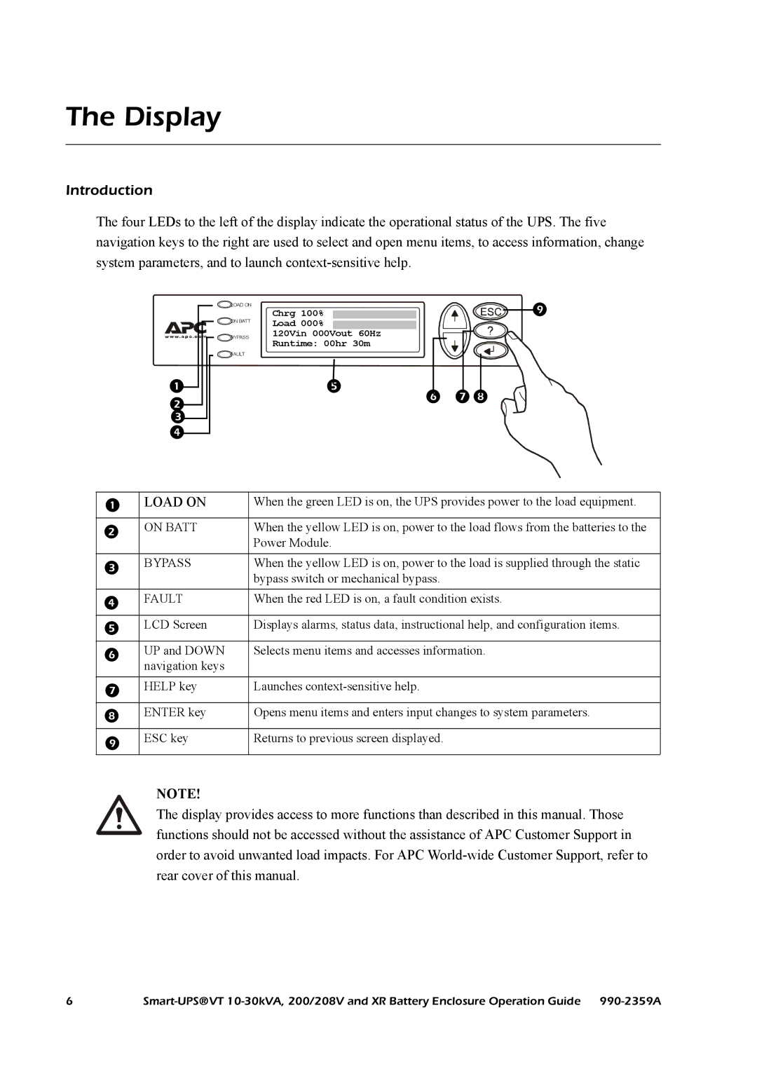
The four LEDs to the left of the display indicate the operational status of the UPS. The five navigation keys to the right are used to select and open menu items, to access information, change system parameters, and to launch
|
|
|
|
![]() LOAD ON
LOAD ON
ON BATT
BYPASS
FAULT
Chrg 100% ![]() Load 000%
Load 000% ![]() 120Vin 000Vout 60Hz Runtime: 00hr 30m
120Vin 000Vout 60Hz Runtime: 00hr 30m
![]()
![]()
|
| LOAD ON | When the green LED is on, the UPS provides power to the load equipment. |
|
|
|
| ON BATT | When the yellow LED is on, power to the load flows from the batteries to the |
|
| Power Module. |
| BYPASS | When the yellow LED is on, power to the load is supplied through the static |
|
| bypass switch or mechanical bypass. |
| FAULT | When the red LED is on, a fault condition exists. |
|
|
|
| LCD Screen | Displays alarms, status data, instructional help, and configuration items. |
|
|
|
| UP and DOWN | Selects menu items and accesses information. |
| navigation keys |
|
| HELP key | Launches |
|
|
|
| ENTER key | Opens menu items and enters input changes to system parameters. |
|
|
|
| ESC key | Returns to previous screen displayed. |
|
|
|
NOTE!
The display provides access to more functions than described in this manual. Those functions should not be accessed without the assistance of APC Customer Support in order to avoid unwanted load impacts. For APC
6 |