Appendix
9.0Appendix
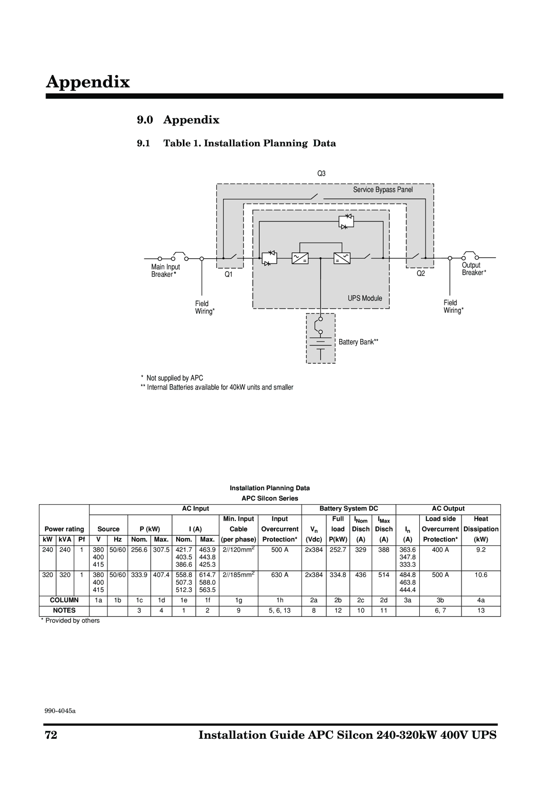
9.1Table 1. Installation Planning Data
Q3
Service Bypass Panel
Main Input |
|
Breaker * | Q1 |
| UPS Module |
| Field |
| Wiring* |
Output
Q2Breaker*
Field
Wiring*
Battery Bank**
*Not supplied by APC
**Internal Batteries available for 40kW units and smaller
Installation Planning Data
APC Silcon Series
|
|
|
|
|
|
|
|
| AC Input |
|
| Battery System DC |
| AC Output | |||||
|
|
|
|
|
|
|
|
|
|
|
|
|
|
|
|
|
|
|
|
|
|
|
|
|
|
|
|
|
|
| Min. Input | Input |
| Full | INom | IMax |
| Load side | Heat |
Power rating | Source | P (kW) | I (A) | Cable | Overcurrent | Vn | load | Disch | Disch | In | Overcurrent | Dissipation | |||||||
kW |
| kVA |
| Pf | V | Hz | Nom. | Max. | Nom. | Max. | (per phase) | Protection* | (Vdc) | P(kW) | (A) | (A) | (A) | Protection* | (kW) |
|
|
|
|
|
|
|
|
|
|
|
|
|
|
|
|
|
|
|
|
240 |
| 240 |
| 1 | 380 | 50/60 | 256.6 | 307.5 | 421.7 | 463.9 | 2//120mm2 | 500 A | 2x384 | 252.7 | 329 | 388 | 363.6 | 400 A | 9.2 |
|
|
|
|
| 400 |
|
|
| 403.5 | 443.8 |
|
|
|
|
|
| 347.8 |
|
|
|
|
|
|
| 415 |
|
|
| 386.6 | 425.3 |
|
|
|
|
|
| 333.3 |
|
|
|
|
|
|
|
|
|
|
|
|
|
|
|
|
|
|
|
|
|
|
320 |
| 320 |
| 1 | 380 | 50/60 | 333.9 | 407.4 | 558.8 | 614.7 | 2//185mm2 | 630 A | 2x384 | 334.8 | 436 | 514 | 484.8 | 500 A | 10.6 |
|
|
|
|
| 400 |
|
|
| 507.3 | 588.0 |
|
|
|
|
|
| 463.8 |
|
|
|
|
|
|
| 415 |
|
|
| 512.3 | 563.5 |
|
|
|
|
|
| 444.4 |
|
|
|
|
|
|
|
|
|
|
|
|
|
|
|
|
|
|
|
| ||
| COLUMN |
| 1a | 1b | 1c | 1d | 1e | 1f | 1g | 1h | 2a | 2b | 2c | 2d | 3a | 3b | 4a | ||
|
|
|
|
|
|
|
|
|
|
|
|
|
|
|
|
|
| ||
| NOTES |
|
|
| 3 | 4 | 1 | 2 | 9 | 5, 6, 13 | 8 | 12 | 10 | 11 |
| 6, 7 | 13 | ||
|
|
|
|
|
|
|
|
|
|
|
|
|
|
|
| ||||
* Provided by others |
|
|
|
|
|
|
|
|
|
|
|
|
|
| |||||
72 | Installation Guide APC Silcon |