External Connection
Terminal Blocks: X003/X004 (Anxiliary Contacts)
When switching Q001, Q002, Q010, Battery Breaker 1 or Battery Breaker 2 from “ON or 1” to “OFF or 0”, the anxiliary contact has to be open BEFORE the corresponding main contacts are opened. When switching Q001, Q002, Q010, Battery Breaker 1 or Battery Breaker 2 the opposite way from “OFF or 0” to “ON or 1”, the anxiliary contact has to close with a maximum delay of 0.5 seconds from the time the corresponding main contacts are closed.
•This type of auxillary contact is called a “late make” contact. (This also means that it will “break early” when activated in opposite direction.)
•This auxillary contact is also called “NORMALLY OPEN” (NO), because the auxillary contact will be open when the main contacts are open.
•Please note that the above term “NORMALLY” has nothing to do with NORMAL UPS OPERATION MODE.
When switching Q003 from “OFF or 0” to “ON or 1”, the anxiliary contact has to open BEFORE the corresponding main contacts are closed. When switching Q003 the opposite way from “ON or 1” to “OFF or 0”, the auxillary contact has to close with a maximum delay of 0.5 seconds from the time when the corresponding main contacts are opened.
•This type of anxiliary contact is called an “early break” contact. (This also means that it will “make late” when activated in the opposite direction.)
•The auxiliary contact is also called “NORMALLY CLOSED” (NC), because the auxiliary contact will be closed when the main contacts are open.
•Please note that the above term “NORMALLY” has nothing to do with NORMAL UPS OPERATION.
X005 (Output Relays)
Battery operation signals are received with a
Maximum nominal voltage on contact circuits is 277VAC. If two different phases are involved, maximum phase to neutral voltage should be below 160VAC. Please note that phase L1 is already present on the System Integration Interface board, supplied from the Service Bypass Panel. Therefore, if a phase is needed for alarm or signal purposes, Phase L1 should be used.
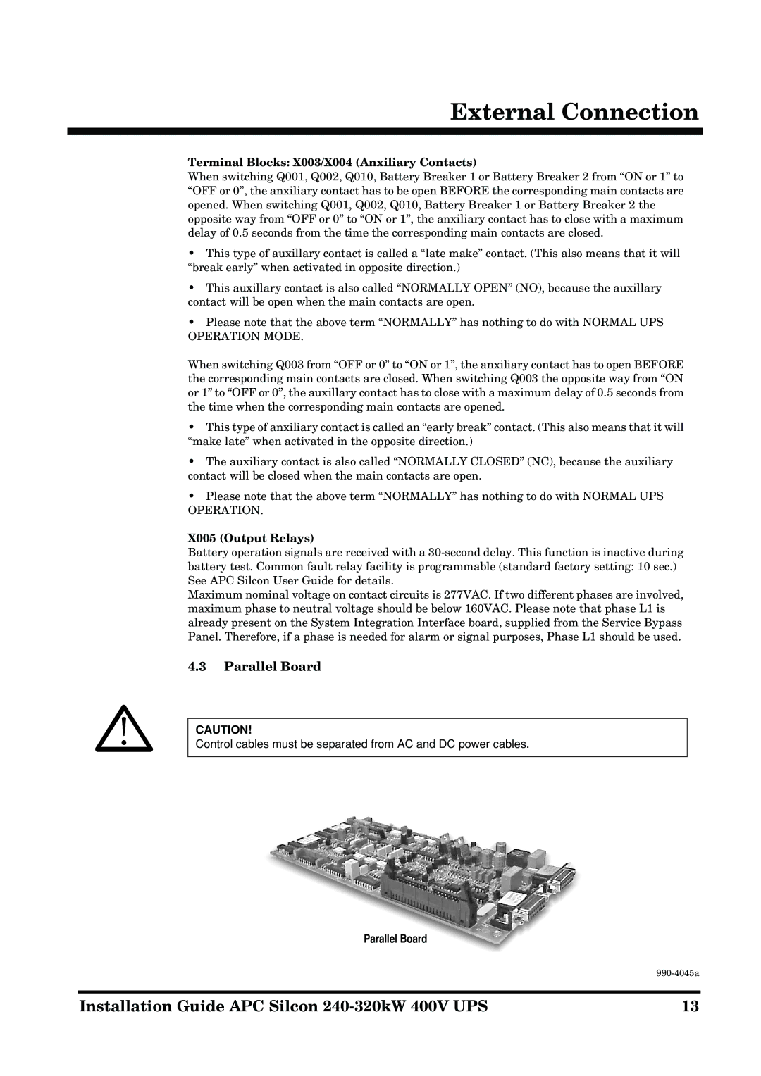
4.3Parallel Board
CAUTION!
Control cables must be separated from AC and DC power cables.
Parallel Board
| |
|
|
Installation Guide APC Silcon | 13 |
