Options/Accessories
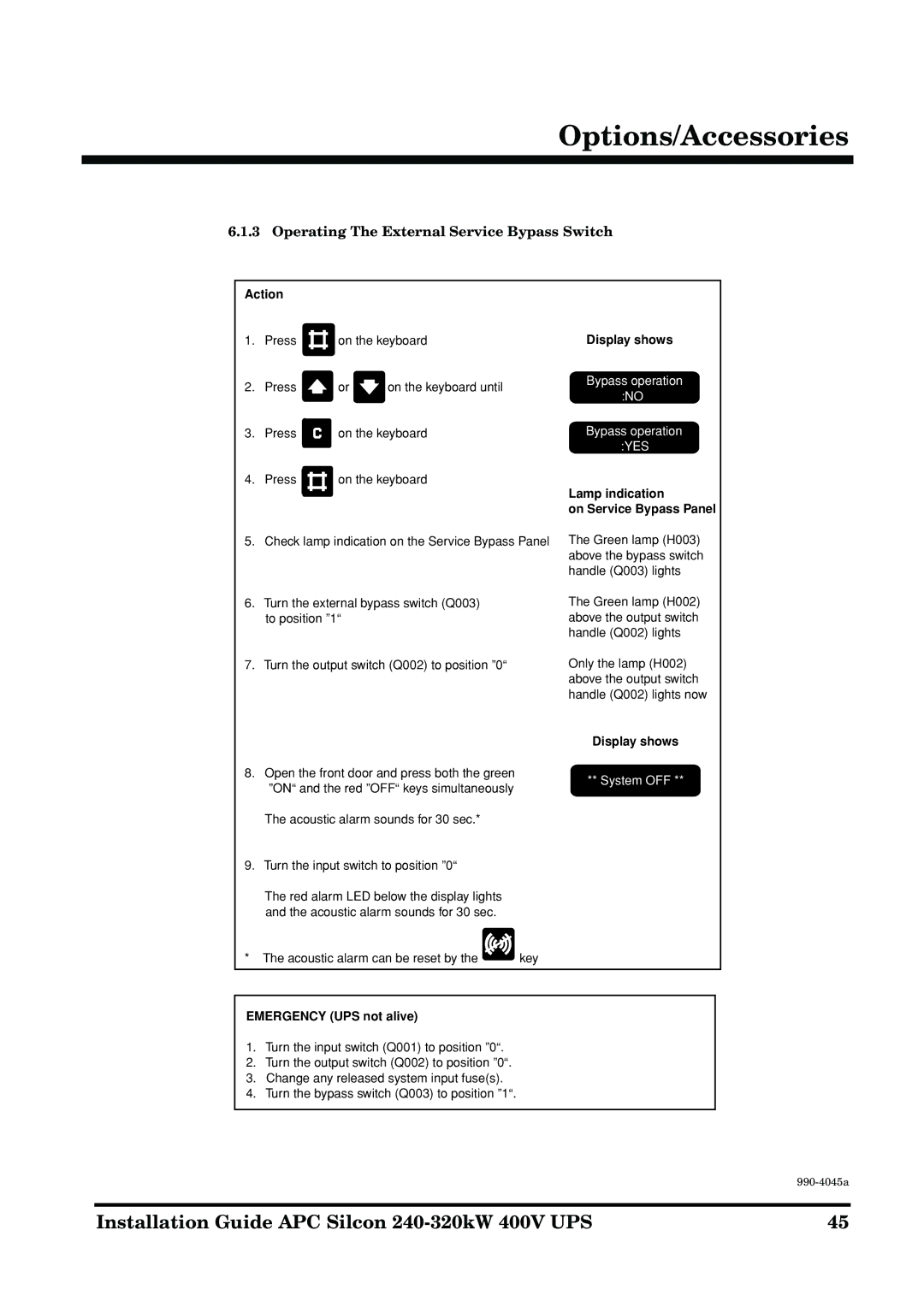
6.1.3 Operating The External Service Bypass Switch
Action |
|
|
|
| |
1. | Press |
| on the keyboard | Display shows | |
| |||||
2. | Press |
| or | on the keyboard until | Bypass operation |
| :NO | ||||
|
|
|
|
| |
3. | Press |
| on the keyboard | Bypass operation | |
|
|
|
|
| :YES |
|
|
|
|
| |
4. | Press |
| on the keyboard | Lamp indication | |
|
|
|
|
| |
|
|
|
|
| |
|
|
|
|
| on Service Bypass Panel |
5. | Check lamp indication on the Service Bypass Panel | The Green lamp (H003) | |||
|
|
|
|
| above the bypass switch |
|
|
|
|
| handle (Q003) lights |
6.Turn the external bypass switch (Q003) to position ”1“
7.Turn the output switch (Q002) to position ”0“
8.Open the front door and press both the green ”ON“ and the red ”OFF“ keys simultaneously
The Green lamp (H002) above the output switch handle (Q002) lights
Only the lamp (H002) above the output switch handle (Q002) lights now
Display shows
** System OFF **
The acoustic alarm sounds for 30 sec.*
9.Turn the input switch to position ”0“
The red alarm LED below the display lights and the acoustic alarm sounds for 30 sec.
* The acoustic alarm can be reset by the | key |
EMERGENCY (UPS not alive)
1.Turn the input switch (Q001) to position ”0“.
2.Turn the output switch (Q002) to position ”0“.
3.Change any released system input fuse(s).
4.Turn the bypass switch (Q003) to position ”1“.
Installation Guide APC Silcon | 45 |
