2.3 Controller
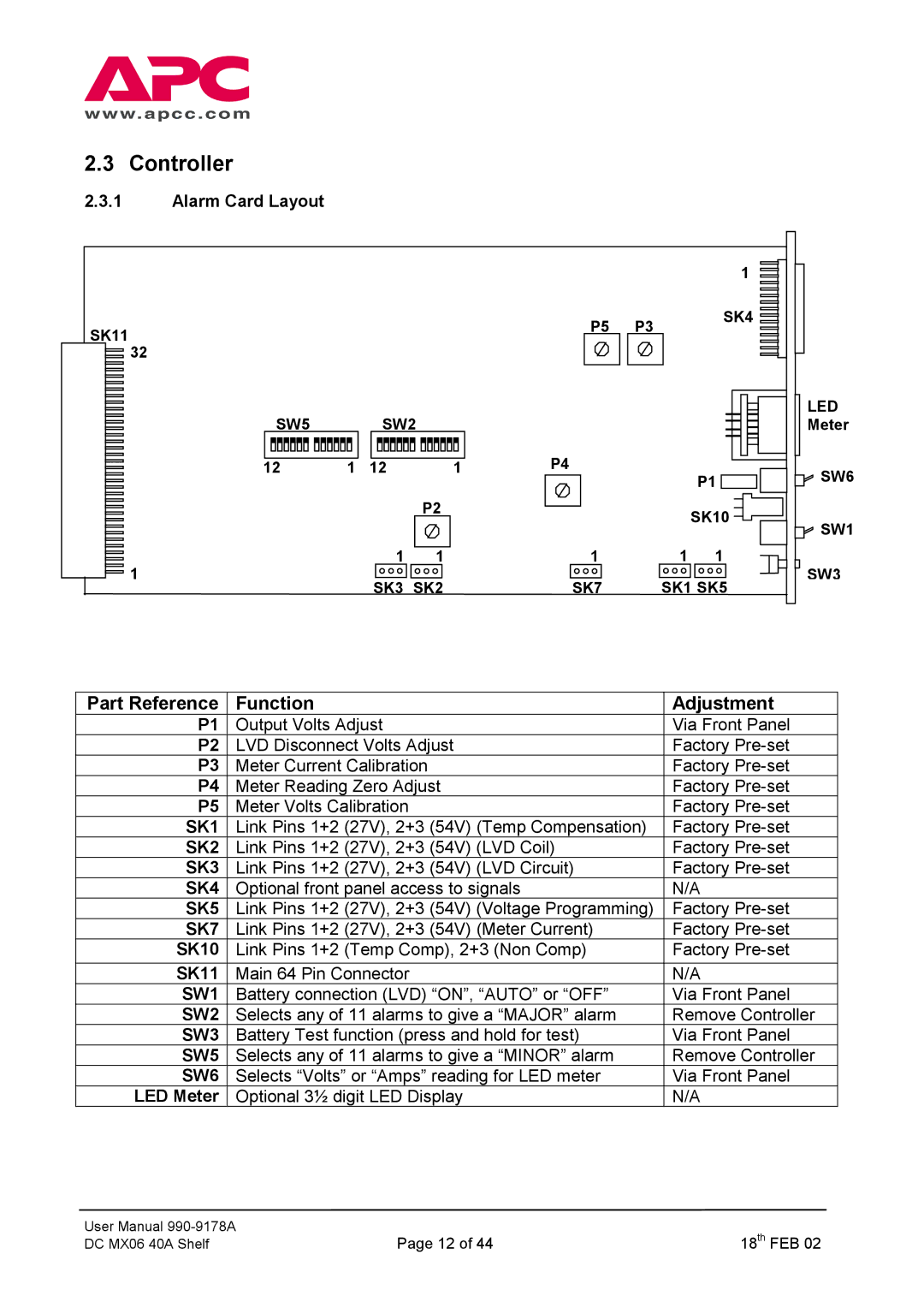
2.3.1Alarm Card Layout
SK11
![]() 32
32
|
| 1 |
P5 | P3 | SK4 |
|
SW5 SW2
|
|
|
|
|
|
|
|
|
|
|
|
|
|
|
|
|
|
|
|
|
|
|
|
|
|
|
12 | 1 | 12 | 1 | |||||
P4
LED
Meter
P1 ![]()
![]()
![]()
![]() SW6
SW6
![]() 1
1
P2
1 1
SK3 SK2
SK10 ![]()
![]()
![]() SW1
SW1
1 | 1 | 1 |
SK7 |
| SW3 |
SK1 SK5 | ||
Part Reference | Function | Adjustment |
P1 | Output Volts Adjust | Via Front Panel |
P2 | LVD Disconnect Volts Adjust | Factory |
P3 | Meter Current Calibration | Factory |
P4 | Meter Reading Zero Adjust | Factory |
P5 | Meter Volts Calibration | Factory |
SK1 | Link Pins 1+2 (27V), 2+3 (54V) (Temp Compensation) | Factory |
SK2 | Link Pins 1+2 (27V), 2+3 (54V) (LVD Coil) | Factory |
SK3 | Link Pins 1+2 (27V), 2+3 (54V) (LVD Circuit) | Factory |
SK4 | Optional front panel access to signals | N/A |
SK5 | Link Pins 1+2 (27V), 2+3 (54V) (Voltage Programming) | Factory |
SK7 | Link Pins 1+2 (27V), 2+3 (54V) (Meter Current) | Factory |
SK10 | Link Pins 1+2 (Temp Comp), 2+3 (Non Comp) | Factory |
SK11 | Main 64 Pin Connector | N/A |
SW1 | Battery connection (LVD) “ON”, “AUTO” or “OFF” | Via Front Panel |
SW2 | Selects any of 11 alarms to give a “MAJOR” alarm | Remove Controller |
SW3 | Battery Test function (press and hold for test) | Via Front Panel |
SW5 | Selects any of 11 alarms to give a “MINOR” alarm | Remove Controller |
SW6 | Selects “Volts” or “Amps” reading for LED meter | Via Front Panel |
LED Meter | Optional 3½ digit LED Display | N/A |
User Manual | Page 12 of 44 | 18th FEB 02 |
DC MX06 40A Shelf |