4.1.3.2Front access connection
To connect the input supply to the MX06 40A Shelf proceed as follows:
•The AC input current to the system should also be limited by an appropriate device in the event of a short circuit as defined in EN60950 to protect the internal wiring of the end use equipment. The device(s) should be rated accordingly.
•Ensure that the AC supply intended for connection is isolated, locked off and under single operator control.
•The main circuit board should have been configured for
•Strip the ends of the AC Input cables to be connected to the Input terminal block.
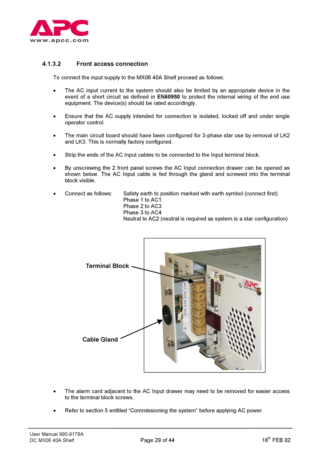
•By unscrewing the 2 front panel screws the AC Input connection drawer can be opened as shown below. The AC Input cable is fed through the gland and screwed into the terminal block visible.
• Connect as follows: | Safety earth to position marked with earth symbol (connect first) |
| Phase 1 to AC1 |
| Phase 2 to AC3 |
| Phase 3 to AC4 |
| Neutral to AC2 (neutral is required as system is a star configuration) |
Terminal Block
Cable Gland ![]()
•The alarm card adjacent to the AC Input drawer may need to be removed for easier access to the terminal block screws.
•Refer to section 5 entitled “Commissioning the system” before applying AC power.
User Manual | Page 29 of 44 | 18th FEB 02 |
DC MX06 40A Shelf |
