INPUT FREQUENCY/OUTPUT FREQUENCY Screen
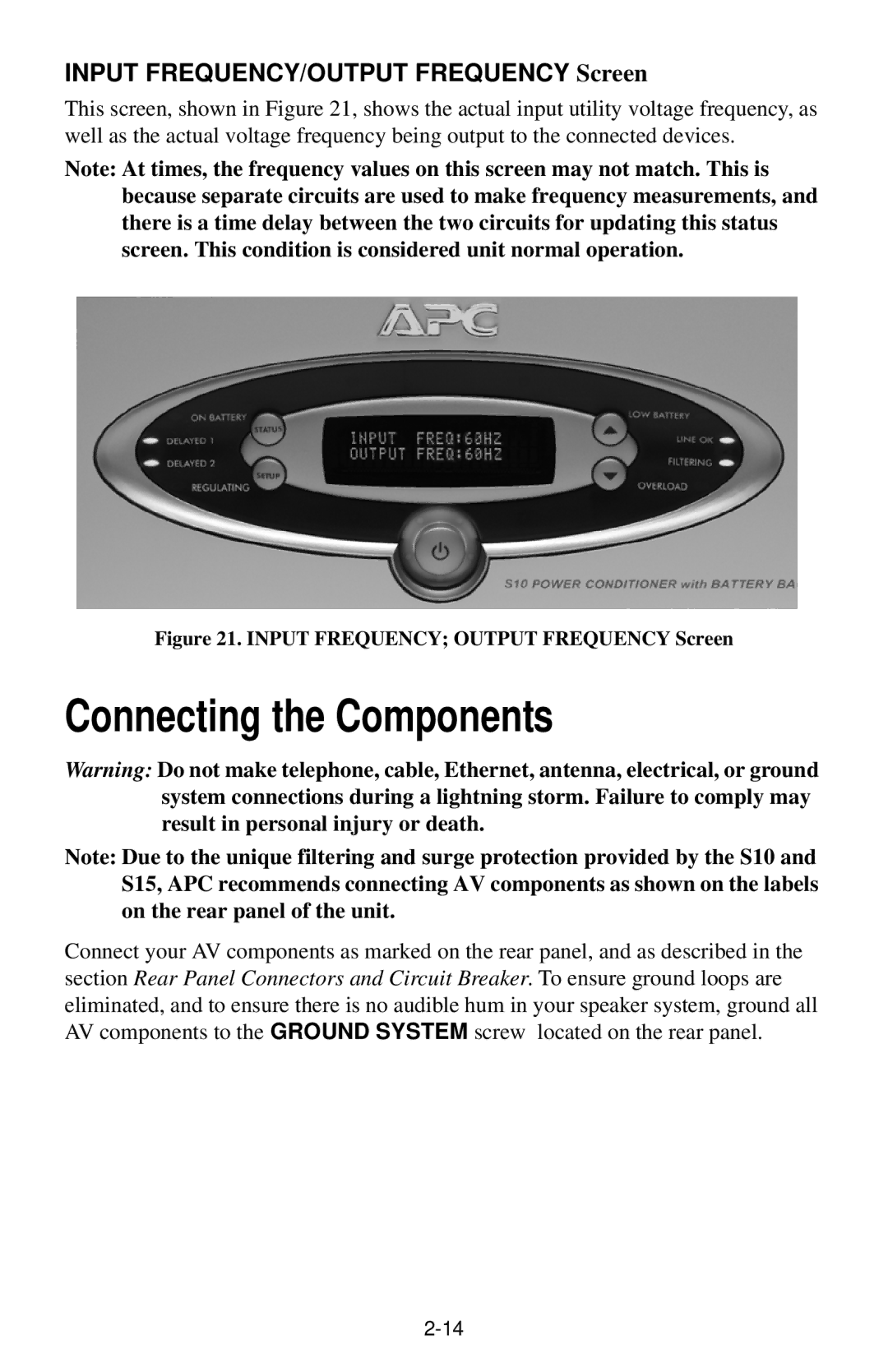
This screen, shown in Figure 21, shows the actual input utility voltage frequency, as well as the actual voltage frequency being output to the connected devices.
Note: At times, the frequency values on this screen may not match. This is because separate circuits are used to make frequency measurements, and there is a time delay between the two circuits for updating this status screen. This condition is considered unit normal operation.
Figure 21. INPUT FREQUENCY; OUTPUT FREQUENCY Screen
Connecting the Components
Warning: Do not make telephone, cable, Ethernet, antenna, electrical, or ground system connections during a lightning storm. Failure to comply may result in personal injury or death.
Note: Due to the unique filtering and surge protection provided by the S10 and S15, APC recommends connecting AV components as shown on the labels on the rear panel of the unit.
Connect your AV components as marked on the rear panel, and as described in the section Rear Panel Connectors and Circuit Breaker. To ensure ground loops are eliminated, and to ensure there is no audible hum in your speaker system, ground all AV components to the GROUND SYSTEM screw located on the rear panel.