Appendix E - Private digital circuits | AM64/128A User Manual |
|
|
APPENDIX E
Use on X.21/X.21bis digital circuits - External Timing Configuration
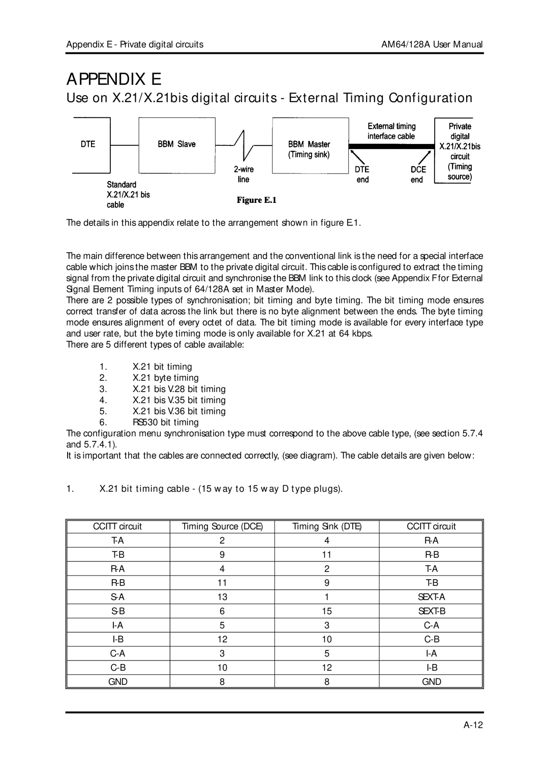
The details in this appendix relate to the arrangement shown in figure E.1.
The main difference between this arrangement and the conventional link is the need for a special interface cable which joins the master BBM to the private digital circuit. This cable is configured to extract the timing signal from the private digital circuit and synchronise the BBM link to this clock (see Appendix F for External Signal Element Timing inputs of 64/128A set in Master Mode).
There are 2 possible types of synchronisation; bit timing and byte timing. The bit timing mode ensures correct transfer of data across the link but there is no byte alignment between the ends. The byte timing mode ensures alignment of every octet of data. The bit timing mode is available for every interface type and user rate, but the byte timing mode is only available for X.21 at 64 kbps.
There are 5 different types of cable available:
1.X.21 bit timing
2.X.21 byte timing
3.X.21 bis V.28 bit timing
4.X.21 bis V.35 bit timing
5.X.21 bis V.36 bit timing
6.RS530 bit timing
The configuration menu synchronisation type must correspond to the above cable type, (see section 5.7.4 and 5.7.4.1).
It is important that the cables are connected correctly, (see diagram). The cable details are given below:
1.X.21 bit timing cable - (15 way to 15 way D type plugs).
CCITT circuit | Timing Source (DCE) | Timing Sink (DTE) | CCITT circuit |
2 | 4 | ||
|
|
|
|
9 | 11 | ||
|
|
|
|
4 | 2 | ||
|
|
|
|
11 | 9 | ||
|
|
|
|
13 | 1 | ||
|
|
|
|
6 | 15 | ||
|
|
|
|
5 | 3 | ||
|
|
|
|
12 | 10 | ||
|
|
|
|
3 | 5 | ||
|
|
|
|
10 | 12 | ||
|
|
|
|
GND | 8 | 8 | GND |
|
|
|
|